Table of Contents
Advertisement
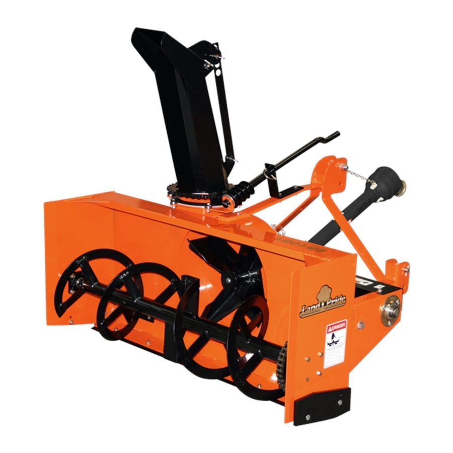
Snow Blowers
SB1051, SB1064, SB1574, & SB2584 with S/N 881641+
37078
SB10 Series Shown with Optional Hydraulic Chute Rotor, Hydraulic Deflector, & Skid Shoes
Read the Operator's Manual entirely. When you see this symbol,
!
the subsequent instructions and warnings are serious - follow
without exception. Your life and the lives of others depend on it!
Cover illustration may show optional
equipment not supplied with standard unit.
© Copyright 2016
Table of Contents
Printed
10/12/16
Operator's Manual
SB10 Series
SB15 Series
370-430M
SB25 Series
Advertisement
Table of Contents

Related Manuals for Land Pride SB10 Series


Summary of Contents for Land Pride SB10 Series
- Page 1 Table of Contents Snow Blowers SB1051, SB1064, SB1574, & SB2584 with S/N 881641+ 37078 SB10 Series Shown with Optional Hydraulic Chute Rotor, Hydraulic Deflector, & Skid Shoes 370-430M Operator’s Manual Read the Operator’s Manual entirely. When you see this symbol, the subsequent instructions and warnings are serious - follow without exception.
- Page 2 Land Pride assumes no responsibility for errors or omissions. Neither is any liability assumed for damages resulting from the use of the information contained herein. Land Pride reserves the right to revise and improve its products as it sees fit. This publication describes the state of this product at the time of its publication, and may not reflect the product in the future.
-
Page 3: Safety At All Times
The QR code below will link you to Manual for this equipment. Download the appropriate App on your camera phone, available dealers for Land Pride open the App, point your phone on the QR code, and take a picture. products. -
Page 4: Use A Safety Chain
Replace parts only with genuine Work in a clean dry area. rating equal to or greater than the Land Pride Parts. Do not alter Land gross weight of the towed Lower attached implement to the Pride equipment or replace parts machinery. - Page 5 Table of Contents Important Safety Information These are common practices that may or may not be applicable to the products described in this manual. Wear Avoid High Prepare for Emergencies Protective Equipment Pressure Fluids Hazard Be prepared if a fire starts. ...
-
Page 6: Safety Labels
Spray soapy water onto the cleaned area. all damaged or missing labels. Order new labels from your Peel backing from label and press label firmly onto the nearest Land Pride dealer. To find your nearest dealer, surface. visit our dealer locator at www.landpride.com. -
Page 7: Important Safety Information
Table of Contents Important Safety Information 37081 818-858C Warning: To Prevent Serious Injury or Death 37081 818-634C Danger: Rotating Auger 37079 818-130C Caution: To avoid Injury or Machine Damage 37081 10/12/16 SB1051, SB1064, SB1574, & SB2584 with S/N 881641+ Snow Blowers 370-430M... - Page 8 Table of Contents Important Safety Information 848-840C Danger: Hands in Chute 2-Places: On both sides of chute 37082 818-132C Danger: Thrown Object Hazard 2-Places: On both sides of chute 37082 Hydraulic Cylinder Location Hydraulic Motor Location 848-747C Warning: High Pressure Fluid Hazard Used only with hydraulic motor and hydraulic cylinders.
-
Page 9: Using This Manual
Table of Contents Introduction Introduction Land Pride welcomes you to the growing family of new customer service or repair parts are required. Your Land product owners. This Snow Blower has been designed Pride dealer has trained personnel, repair parts, and with care and built by skilled workers using quality equipment needed to service the implement. -
Page 10: Section 1: Standard Assembly & Set-Up
Tractor Horsepower Rating SB10 Series ..... 18 to 32 HP SB15 Series ..... . .30-59 HP... - Page 11 Table of Contents Section 1: Standard Assembly & Set-up SB10 Chute Assembly SB15 & 25 Chute Assembly Refer to Figure 1-2: Refer to Figure 1-3: Remove bearing strap (#2A) from Snow Blower Remove rotational stop (#3) and bearing strap (#2A) housing.
-
Page 12: Section 2: Optional Assembly & Set-Up
SB15 & SB25 Series: Attach to hole “B”. align properly. • SB10 Series: Attach to hole “C”. 6. Tighten set screws (#7) & bolts (#8, #9A, #9B, & #10) Draw nut up snug, do not tighten at this time. to the correct torque. - Page 13 Table of Contents Section 2: Optional Assembly & Set-up 372218 Hydraulic Chute Rotation Assembly (SB2584 Shown) Figure 2-3 Hydraulic Chute Rotation Refer to Figure 2-3: IMPORTANT: Adjustment screws on hydraulic motor (#7) are preset at the factory. Do not change factory settings.
- Page 14 Table of Contents Section 2: Optional Assembly & Set-up 37089 Hydraulic Deflector Assembly 37088 Figure 2-5 Electric Deflector Assembly Figure 2-6 Hydraulic Deflector Assembly Electric Deflector Assembly Refer to Figure 2-5: Screw O-ring end of 9/16" elbows (#4A & #4B) into Refer to Figure 2-6: hydraulic ports of cylinder (#3).
- Page 15 Table of Contents Section 2: Optional Assembly & Set-up 37087 Manual Deflector Assembly 37093 Figure 2-7 Inner Skid Shoe Assembly Figure 2-9 Manual Deflector Assembly Refer to Figure 2-7: Skid Shoes, Inner Attach lower single hole in adjustment deflector Refer to Figure 2-9: arm (#1) to lower discharge chute lug “A”...
- Page 16 Table of Contents Section 2: Optional Assembly & Set-up 37090 Lower Wear Bar Assembly Figure 2-10 Wear Bar, Lower Refer to Figure 2-10: Attach lower wear bar (#1) to bottom of Snow Blower frame with 3/8"-16 x 1" GR5 plow bolts (#2) and hex flange lock nuts (#3).
- Page 17 Table of Contents Section 2: Optional Assembly & Set-up 37097 3-Point Hitch Set-up (Shown with 3-Point Hitch Fully Extended) Figure 2-12 Extend/Retract 3-Point Hitch Frame 4. Reinsert 1/2"-13 x 2 1/2" GR5 carriage bolts (#4). Secure bolts with spring lock washers (#7) and hex Refer to Figure 2-12: nuts (#5).
-
Page 18: Section 3: Tractor Hook-Up & Unhook
If adjusted too long, the rotational handle can come in contact with tractor or create a pinch point between tractor and Snow NOTE: Land Pride’s Quick Hitch can be attached to Blower causing bodily injury. the tractor to provide quick and easy 3-point ... -
Page 19: Leveling The Snow Blower
Table of Contents Section 3: Tractor Hook-up & Unhook Leveling The Snow Blower Refer to Figure 3-1 on page 16: Park tractor on a level surface. Slowly engage tractor Park tractor on solid level ground, place gear selector 3-point lift lever to raise Snow Blower until gearbox in park or set park brake, shut tractor engine off and input shaft is in line and level with tractor PTO shaft. -
Page 20: Shorten Driveline
Table of Contents Section 3: Tractor Hook-up & Unhook Shorten Driveline 2. Assemble the two driveline profiles together with just 1/2 overlapping of the profile tubes as shown. Once Refer to Figure 3-3 on page 18: assembled, measure and record maximum allowable Be sure to check driveline collapsed length first. -
Page 21: Hydraulic Hook-Up
Table of Contents Section 3: Tractor Hook-up & Unhook Hydraulic Hook-up Refer to Figure 3-6: Find a suitable location to mount control box (#1) on the tractor. Usually this would be close to the DANGER operator’s right-hand side on the tractor fender or Hydraulic fluid under high pressure can penetrate skin. - Page 22 Table of Contents Section 3: Tractor Hook-up & Unhook Unhooking Snow Blower Remove top center hitch pin keeper and hitch pin. If provided, place center 3-point link in tractor’s holding See “Long Term Storage” on page 34 before clip. parking Snow Blower for a long period. 8.
-
Page 23: Section 4: Adjustments
Table of Contents Section 4: Adjustments Section 4: Adjustments Hitch Pin Locations Bushing Is Located In Lower Hitch Holes The lower 3-point hitch pins and upper center bolt-on For Quick Hitch. bushing can be arranged in the A-frame hitch three different ways depending on user preference. - Page 24 Table of Contents Section 4: Adjustments Chute Rotation Deflector The deflector can be tilted up or down to direct blown snow up close or far away. This is accomplished in one of WARNING three ways depending upon which option was Never rotate chute to throw snow at the tractor.
-
Page 25: Inner Skid Shoes
Table of Contents Section 4: Adjustments 37100 37099 Inner Skid Shoe Adjustment Outer Skid Shoe Adjustment Figure 4-5 Figure 4-6 Inner Skid Shoes Outer Skid Shoes Refer to Figure 4-5: Refer to Figure 4-6: Disengage PTO and park on level ground. Disengage PTO and park on level ground. - Page 26 Table of Contents Section 4: Adjustments 37101 37102 Drive Chain Take-up Adjustment Figure 4-8 Drive Chain Take-up Refer to Figure 4-8: Outer Wear Bar Adjustment IMPORTANT: Do not over tension drive chain. A Figure 4-7 tight drive chain will overload drive shaft, auger shaft, and bearings, and accelerate chain and Outer Wear Bars sprocket wear.
-
Page 27: Operating Checklist
Table of Contents Section 5: Operating Instructions Section 5: Operating Instructions Operating Checklist Check for bent, broken, and extreme wear on auger flighting and impeller. Repair auger and impeller as Hazard control and accident prevention are dependent required. upon the awareness, concern, prudence, and proper 8. -
Page 28: Section 5: Operating Instructions
Table of Contents Section 5: Operating Instructions Safety Information DANGER Do not lift 3-point Snow Blower fully up with driveline DANGER engaged. A Snow Blower raised too high can cause rotating Do not engage tractor PTO while hooking-up and unhooking u-joints to break apart and throw components at high speeds driveline or while someone is standing near the driveline. - Page 29 Table of Contents Section 5: Operating Instructions WARNING WARNING Keep people and animals away while removing snow. Never Never pile snow where it obstructs visibility of traffic. Never operate Snow Blower with chute throwing snow towards pile snow near fire hydrants, mailboxes, water drains, shut-off animals or people.
-
Page 30: General Operator Instructions
Table of Contents Section 5: Operating Instructions It is important that you know the area where snow is to be IMPORTANT: Check driveline coupling bolt at the removed and what lies beneath the snow. If possible, gearbox input shaft daily to verify if it is tight and survey the area ahead of the snow. - Page 31 PTO, and begin traveling blowing snow. With a little practice you will be pleased with what you and your Land Pride Snow Blower can do. Whether you are done blowing snow, need to take a break, or just need to...
-
Page 32: Section 6: Maintenance & Lubrication
Repair or replace impeller before it causes CAUTION structural damage to the Snow Blower housing. Do not alter Land Pride equipment or replace parts with other 4. Check auger flighting (#3) and auger paddles (#2) for brands. Doing so can adversely affect its performance and/or wear, structural cracks, bending, and breakage. -
Page 33: Shearbolt Protection
Chute bearings (#1) rotates with the chute. Should a 33302 bearing stop rotating, remove ice & snow build-up around bearing. Have your nearest Land Pride Service Center Driveline Shearbolt Replacement replace the bearing if it continues to not rotate. Figure 6-4 10/12/16 SB1051, SB1064, SB1574, &... -
Page 34: Drive Chain
4. Inspect drive chain for wear or have your nearest bar (#1) shown in Figure 6-9 on page 34. Land Pride service center inspect the drive chain. A worn drive chain will accelerate sprocket wear. 5. Install new inner skid shoe on the right-hand side of Replace worn drive chain when needed. - Page 35 Table of Contents Section 6: Maintenance & Lubrication 37092 37101 Outer Skid Shoe Replacement Outer Wear Bar Replacement Figure 6-7 Figure 6-8 Outer Skid Shoes (Optional) Outer Wear Bars (Optional) Refer to Figure 6-7: Refer to Figure 6-8: Outer Skid Shoe Part Numbers Outer Wear Bar Part Numbers Part No.
-
Page 36: Long Term Storage
TU, QT, or GL to the end of the aerosol part number. hardened steel wear bar and lower steel wear bar) in 51", 64", 74" & 84" lengths. See your nearest Land Pride Land Pride Aerosol Touch-up Paint dealer for part numbers and pricing. - Page 37 Table of Contents Section 6: Maintenance & Lubrication Lubrication Lubrication Multi-purpose Multi-purpose Multi-purpose Intervals in hours at which spray lube grease lube oil lube lubrication is required Legend Hours Shearbolt Sprocket Hub 1 - Zerk Type of Lubrication: Multi-purpose Grease Quantity = 2 Pumps 33249 Hours...
- Page 38 Table of Contents Section 6: Maintenance & Lubrication 33293 Required Do Not Overfill Gearbox NOTE: Do not overfill! Snow Blower should be level when checking oil. Oil expands when hot, therefore, always check oil level when cold. SB1051 & SB1064 Gearbox Remove oil level plug shown with arrow.
-
Page 39: Section 7: Specifications & Capacities
Table of Contents Section 7: Specifications & Capacities Section 7: Specifications & Capacities SB10, SB15, & SB25 Series Specifications & Capacities Model No. Model SB1051 Model SB1064 Model SB1574 Model SB2584 Working Width 51" 64" 74" 84" Overall Width 52 3/4" 65 3/4"... - Page 40 Table of Contents Section 7: Specifications & Capacities SB1051 = 56 1/2" SB1064 = 69 1/2" SB1574 = 79 1/2" SB2584 = 89 3/4" SB1051 = 64 1/2" SB1064 = 64 1/2" SB1574 = 71" SB2584 = 76 1/4" SB1051 = 53" SB1064 = 53"...
-
Page 41: Section 8: Features & Benefits
Table of Contents Section 8: Features & Benefits Section 8: Features & Benefits SB10, SB15, & SB25 Series Features Benefits Quality Comer Gearbox Provides long life, durability construction. Greasable bearings Less drag and extends life of unit. Adjustable 3-point hitch Operator may set the distance between tractor and Snow Blower to his/her preference. -
Page 42: Section 9: Torque Values Chart
Table of Contents Section 9: Torque Values Chart Section 9: Torque Values Chart Torque Values Chart for Common Bolt Sizes Bolt Head Identification Bolt Head Identification 10.9 Bolt Size Bolt Size (inches) Grade 2 Grade 5 Grade 8 (Metric) Class 5.8 Class 8.8 Class 10.9 in-tpi... -
Page 43: Warranty
This Warranty is limited to the repair or replacement of any defective part by Land Pride and the installation by the dealer of any such replacement part, and does not cover common wear items such as blades, belts, tines, etc. Land Pride reserves the right to inspect any equipment or parts which are claimed to have been defective in material or workmanship. - Page 44 Corporate Office: P.O. Box 5060 Salina, Kansas 67402-5060 USA www.landpride.com...
Need help?
Do you have a question about the SB10 Series and is the answer not in the manual?
Questions and answers