
Related Manuals for BN Products SIGMA DCM 40


Summary of Contents for BN Products SIGMA DCM 40
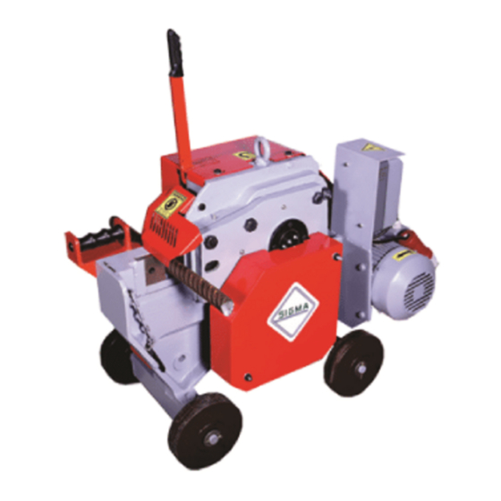
- Page 1 SIGMA DCM 40 MECHANICAL REBAR CUTTING MACHINE OPERATING AND MAINTENANCE MANUAL Supplied by BN Products-USA, LLC 3450 Sabin Brown Rd. Wickenburg, AZ 85390 (800) 992-3833 or (928) 684-2813...
-
Page 2: Table Of Contents
TABLE OF CONTENTS Heading : Page No: 1. Machine Assembly. 1.1.Machine assembly. 1.2.Sequence of machine operating procedures. 2. Technical data. 3. Equipment to accompany the machine. 4. Correct and wrong cutting forms 5. Disallowed operations on the machine 6. Warranty conditions: 7. - Page 3 DCM 40 MECHANICAL REBAR CUTTING MACHINE : DCM 40 Mechanical Rebar cutting machine is manufactured only for the purposes of cutting the Rebar. The use of the machine for other purposes is not permitted. The machine can be easily transported within the short distances under the site conditions by the help of the wheels.
-
Page 4: Machine Assembly
1.1 Machine Assembly: • The machine is to be balanced by feeding with wedges underneath in a manner to disconnect the wheels from the ground on a smooth surface. (see Figure 1) • The electrical connection of the machine should be installed by the authorized people. Operating voltage should be 415 V. - Page 5 Start- Stop Buttons : Figure : 2 Machine cutting capacity : Diameter Of Rebar 650 N/mm 850 N/mm Ø40(#11) X 1 Ø32(#10) X 1 Ø32(#10) X 1 Ø25(#8) X 1 Ø25(#8) X 1 Ø16(#5) X 1 Ø12(#4) X 4 Ø12(#4) X 3 Ø10(#3) X 4 Ø10(#3) X 3 Ø6(#2) X 6...
-
Page 6: Technical Data
2. TECHNICAL DATA • Machine Type: DCM 40 • Machine Designation: Mechanical Rebar Cutting Machine Blade Size: Width: 85 mm Length: 85 mm Thickness: 20 mm Belt Used: V-belt: A-49 Machine Dimensions: Width: 560 mm Length: 1020 mm Height: 750 mm Weight: 350 kg Motor specifications: Motor power: 5.5 Kw... -
Page 7: Correct And Wrong Cutting Forms
4. Correct placement of the steel between the blades: Figure: 3 MOVABLE BLADE FIXED BLADE SHIELD STEEL CORRECT CUTTING Wrong placement of the steel between the blades: WRONG CUTTING For multi-cutting operations, place one steel on the top of the other in an amount indicated in the capacity plate. -
Page 8: Disallowed Operations On The Machine
5. DISALLOWED OPERATIONS ON THE MACHINE: ▼No cutting work should be conducted without closing the Protective Shield. ▼ The machine will be powered off and the electrical system will be switched off during a blade replacement or maintenance work. ▼ No one should be allowed to stand in front of the machine during a cutting work. -
Page 9: Warranty Conditions
6. WARRANTY CONDITIONS: The manufacturer accepts the warranty and liability only if the following conditions are observed ▼ The Guards fitted on the machine are never removed. ▼ The warning signals are observed. ▼ The machine is not operated without lubricants. ▼... -
Page 10: Protectors To Be Used During Operation Of The Machine
7. PROTECTORS TO BE USED DURING OPERATION OF THE MACHINE 7.1The protective clothing • Hard hat • Glasses • Safety Shoes • Gloves The above mentioned protectors are to be used. Otherwise, there is a risk of injury and body harm. -
Page 11: Checks & Adjustments On The Machine And Blade Replacement
9. CHECKS & ADJUSTMENTS ON THE MACHINE AND BLADE REPLACEMENT 9.1 Belt adjustment: The V-belts placed on the machine are loosened over time. Also the belt adjustment is necessary as it will be misadjusted after the belt replacements. If the belt is loose, it causes noise during the running of the machine and shortens the life time of the belt. -
Page 12: Demounting Of V-Belt
9.2 Sequence of demounting of the V-belt from the machine: 1. Demount the protective cover at the pulley side of the machine. 2. Loosen the motor connection bolt. 3. Unscrew the nut of the motor adjustment bolt. 4. Make the pulleys close to each other by turning the motor adjustment bolt. 5. -
Page 13: Maintenance Of The Machine
10. MAINTENANCE OF THE MACHINE: It is of great importance that the maintenance is performed properly in order to increase the service life of the machine and ensure a safe cutting work. We recommend that each user installs a reliable system for the control and maintenance of the machine. The following instructions are provided only for reference purposes. -
Page 14: Annual Maintenance Of The Machine
• Demount the protective covers of the machine and remove the contaminated oil on the movable parts and re-lubricate them. • Check the movable running gears, engagers and carriers, machine bodies and machine components for bluntness, breaks and cracks. • Check if cavities are formed due to wear on the bronze bearings of the machine, and replace the bronze bearings if so. -
Page 15: Fault Analyses And Remedies
11. FAULTS AND REMEDIES: The faults to arise during the operation of the machine and their reasons and remedies are NO FAULT DESCRIPTION REMEDY The power switch is interrupted frequently 1. The power switch may be 1. Check the belts for their interrupted due to overheating of tightness. - Page 16 Machine is noisy when 3. The roller bearings may be 3. Check the roller bearings. failed. running. 4. The machine is not lubricated 4. Check and lubricate the machine. enough. 5. The motor fan cover may be 5. Check the motor fan cover. crushed.
-
Page 17: Electrical Diagram
12. ELECTRICAL DIAGRAM:... -
Page 18: Materials List
13. MATERIALS LIST: Part Number Part Name Quantity DCM40-01 Main Body DCM40-02 Roller Bearing(6309 ZZ) DCM40-03 Helix Pinion Gear DCM40-04 10 X 10 X 94 Wedge DCM40-05 Roller Bearing(6211 ZZ) DCM40-06 Helix Gear DCM40-07 Roller Bearing (6313 ZZ) DCM40-08 Spur Pinion DCM40-09 12 X 12 X 38 Wedge DCM40-10... - Page 19 DCM40-33 Engagement Pin DCM40-34 Clutch Spring DCM40-35 Spring Retaining Cover DCM40-36 Allen CSK M10 X 35 DCM40-37 Pulley A2-7” DCM40-38 Motor Connection Stand DCM40-39 Hex Screw M20 X 100 DCM40-40 Hex Nut M20 DCM40-41 Hex Nut M16 DCM40-42 Hex Screw M16 X 100 DCM40-43 Electric Motor 5.5Kw ,1730 Rpm,220/460V, 60 Hz...
- Page 20 DCM40-65 Hand Lever DCM40-66 Spring DCM40-67 Disengagement Mechanism DCM40-68 Disengagement Pin DCM40-69 Disengagement Spring DCM40-70 Disengagement Block DCM40-71 Spacer Dia 20 X 21 Lg DCM40-72 Lever DCM40-73 Protective Cover LH DCM40-74 Hex Screw M10 X 15 DCM40-75 Mounting Angle DCM40-76 Wheel DCM40-77 Washer Dia 50...
- Page 22 14. ELECTRICAL CONNECTION For the main electrical connection, it should be connected to the supply line with an insulated cable of 5x4 mm and then fitted into the socket. ELECTRICAL EARTHING The following procedure should be followed. Connect on end of the earthing to a cooper wire (minimum 16 mm²) to ensure the electrical conductivity.
Need help?
Do you have a question about the SIGMA DCM 40 and is the answer not in the manual?
Questions and answers