Advertisement
Quick Links
Advertisement

Related Manuals for Coolaroo FAIRHAVEN


Summary of Contents for Coolaroo FAIRHAVEN
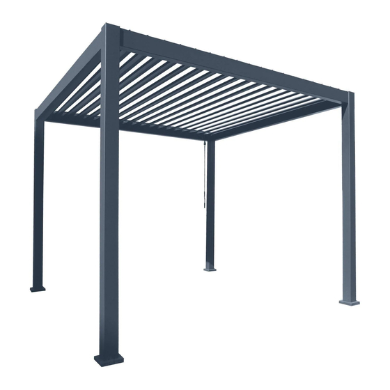
- Page 1 GAZEBO F A I R H A V E N YEAR A S S E M B L Y G U I D E...
-
Page 2: Care And Maintenance
Sun Smart steps: slip on clothing, slop on sunscreen, slap on a hat, slide on sunglasses and seek shade. To register your product, go to coolaroo.com. The product code can be found printed above the barcode on the product packaging, alternatively you can find it on the relevant coolaroo.com product page. - Page 3 2.5m FAIRHAVEN P A R T S S U M M A R Y 4 pcs 4 pcs 4 pcs 45 pcs 1 pc 23 pcs 4 pcs 24 pcs 48 pcs 96 pcs 12 pcs 25 pcs 1 pc...
- Page 6 A S S E M B L Y STEP 1 Check that no parts are missing from the four boxes. Ensure you have the required tools and safety equipment shown in figure 1. STEP 2 Slide a collar (I) over the bottom of one of the leg sections (A) as shown in figure 2, with the rounded part of the collar facing towards the top of the leg.
- Page 7 STEP 3 Lay two of the leg sections (A) on the ground as shown below. Take the (B1) rail and slide each end into position in the grooves along the top of the leg sections. Use large allen key (Y) to affix the four screws on each corner.
- Page 8 STEP 4 Lay down the other two leg sections (A) on the ground as shown. Take the (B2) rail and slide each end into position in the grooves along the top of the leg sections, just like the previous step. Use large allen key (Y) to affix the four screws on each corner.
- Page 9 A S S E M B L Y STEP 5 Working with at least one partner and ensuring everyone is wearing a hard hat, set up two ladders. Lift up one side wall (made up of two legs and a rail) and raise one end of the beam (C) above the opening on the leg section (A).
- Page 10 STEP 6 Move the ladders to the other side of the structure. Install the other beam (C) onto the open end, using the same method as in Step 5.
- Page 11 STEP 7 Find the corner below along the B1 rail with the crank pin hanging down. Remove the screw from the crank pin temporarily. Slide the crank loop (V) over the pin, lining up the holes. Drive the screw through both parts. Insert the hook of the crank handle (H) through the crank loop (V).
- Page 12 A S S E M B L Y STEP 8 Take one of the louvres (D) aside and position as shown below, with the large opening facing up and in front of you. Take the louvre arm plate (L) and position it on the inside of the left end of the louvre.
- Page 13 STEP 9 Move this louvre to the top of the structure, lining up the louvre arm (L) with the crank socket on the B1 rail, just above the crank handle. Insert the crank bolt of the louvre arm into the crank socket. Insert the pin on this end of the louvre into the second hole position on top of the B1 rail.
- Page 14 STEP 10 Back on the other side where the crank handle is, secure the crank bolt from the louvre arm into the socket on the B1 rail using an M6 bolt (U) and washer (T). Tighten with the small allen key (X).
- Page 15 A S S E M B L Y STEP 11 On the other side of the louvre, secure the louvre pin into the second position slot by placing a small cover (M) on top of the slot section, lining up the holes. Screw the cover in place using two M5 screws (P).
- Page 16 STEP 12 For each of the remaining 22 louvres, position a louvre plate (K) on the inside of each end. Affix each of the plates into place using two 18mm screws (Q). ×22 times...
- Page 17 STEP 13 Install one of these louvres into the first position, next to the beam. Ensuring this louvre is in the same orientation as the one already installed, insert the pin on the crank handle end into the first hole position on the B1 rail. Place the pin on the other end of the louvre into the first position slot.
- Page 18 A S S E M B L Y STEP 14 Carefully twist the crank handle to ensure the louvre already installed in the second position is rotating correctly (note, the louvre in the first position is designed to remain closed). Rotate the louvre and leave it open in a vertical position. Install the remaining louvres in the same way as before.
- Page 19 STEP 15 Once all louvres are correctly installed, take the louvre guide rail (G) and line up the holes with the free louvre pins on the crank handle side. Put the louvre guide rail over the pins as shown below. Push the straight section of a humpback pin (S) through the small hole of each pin protruding through the guide rail.
- Page 20 STEP 16 Position an right-angle plate (N) on top of one of the corners. Use three 19mm screws (R) to affix it into place. Repeat for the remaining corners. STEP 17 Secure the feet of the gazebo into the ground. For a hard surface such as concrete or tile, drill holes into the surface through the holes in the feet and install the supplied anchor bolts (W).
- Page 22 The best under the sun Coolaroo is the leader in shade fabric technology. Our extensive range of attractive shade solutions is carefully manufactured to protect your home, garden and family from the harsh sun. coolaroo.com WARNING When assembling and using this product, safety precautions should always be followed to reduce the risk of personal injury and damage to equipment.
Need help?
Do you have a question about the FAIRHAVEN and is the answer not in the manual?
Questions and answers