
Related Manuals for MetLogix Mx200


Summary of Contents for MetLogix Mx200
- Page 1 Mx200 User’s MetLogix Inc 175 Canal Street Manchester, NH 03101 USA Guide Tel: 603.836.4452 Fax: 603.369.6499 info@metlogix.com www.metlogix.com...
- Page 2 The advice, methods and instructions contained in this book might not be suitable for your situation. When in doubt regarding suitability, you are encouraged to consult with a professional where appropriate. Metlogix shall not be liable for any loss of profit or any damages, including but not limited to special, incidental, consequential or other damages.
-
Page 3: Getting Help
Introduction The Mx200 user guide describes the operation of the Mx200 readout. The Mx200 supports manual part positioning and feature measurement under direct user control. While this guide might include some material that doesn’t apply to your specific Mx200 configuration, the concepts explained are applicable to all Mx200 systems. For example, Mx200 systems can be 2 or 3 axis systems with X, Y, Z or X, Y, Q axes. - Page 4 If it becomes necessary to contact your MetLogix distributor or system provider, be prepared to supply the following information: • The Mx200 software version number and serial number. These can be read from the main Setup--> “About” page in the Mx200 software. •...
-
Page 5: User Interface
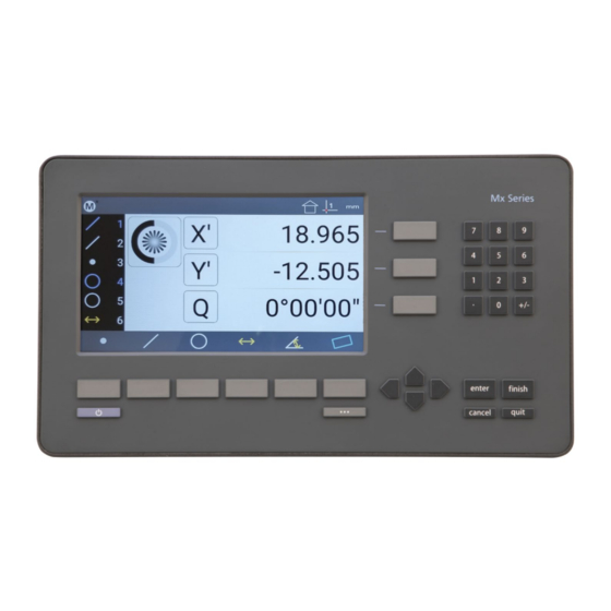
User Interface The Mx200 Software interface consists of a feature list, function buttons, and toolbars for performing and displaying measurements all via a color touchscreen or keypad. Screens Primary screens of the software interface are: • DRO (Home screen) •... - Page 6 Single Press to Power On. When On, Single Press for Screen Off, Long Press for Power Off. Soft Keys(1-6) Executes the softkey button commands/selection displayed above the key. DRO Keys Execute X/Y/Z/Q zerroing funciton. Select functions as vertical softkeys. Menu Button Displays or advances the Softkey Menu. Long press to enter Mx200 Setup.
- Page 7 When the “Desktop” setting for a particular function is set to “Bottom” or “Both” it will be displayed in the Mx200’s “Extra Functions” menu. This menu can be displayed by pressing the Menu key once. Additional keypresses of the Menu button will cycle through the pages of the Extra Functions menu.
- Page 8 The Send button initiates the RS232 send function. Ref Frame Button The Ref Frame button toggles the Abs/Inc datum frame. The DMS/DD button toggles between Degrees Minutes DMS/DD Button Seconds and Decimal Degrees mode. Setup Button The Setup button navigates to the Mx200 setup screen.
- Page 9 How to Probe/Measure features Probing Features Point entry screen Once you have selected a feature to measure, points can be entered by lining up the crosshair on your system then pressing either the Enter button, or the large point counter, as seen in the screen below. When you have entered enough points, press the green check mark or the Finish key.
-
Page 10: Creating Features
Pro-Tip: if you press the Diameter “D” button, or soft key, you will toggle from Diameter to Radius for the measured circle. In this screen you will also see a graphical representation of the circle with the points used for the calculation. A circle requires a minimum of three point. - Page 11 Performing Constructions A common measurement request is to construct a bolt hole pattern from three or more circles. The following example procedure will explain the general sequence that applies to all other supported feature constructions. • Step 1: Measure three circles. •...
- Page 12 Datuming Creating a “Datum”, or zero point, is an essential part of coordinate metrology. When measuring rectangular parts, the first step is often to “Skew” the part or mathematically align the part as it sits on your stage, and then set the origin(or datum) of your part coordinate system.
- Page 13 Performing a Skew Alignment on a Line Feature To probe a skew alignment line: Step 1: Press the Measure Line button. • • Step 2: Probe points well distributed along the entire length of the desired part alignment edge (X axis in the example below).
- Page 14 • Step 3: Press the “Finish” button to complete the line construction. The line will be added to the Feature list and shown in the Feature Detail screen. Step 4: Zero the line angle by pressing the Angle value button to align the part to the X axis. The Angle value •...
- Page 15 • Step 2: Press the Datum Selection button( ) to choose a datum (datum 1 in this example). Step 3: Press the X' and Y' value buttons to zero the center point of the selected feature as a datum. • Presetting a feature location A part datum can also be established by presetting a position directly on any feature's X and Y coordinates.
- Page 16 Tolerancing Use the following steps to apply an X Y Positional Tolerance and Diameter Size tolerance to a measured circle: • Step 1: Skew and datum your part. • Step 2: For this example measure the circle that you want to apply the tolerance to. Step 3: While in the feature detail screen, press the tolerance button( •...
- Page 17 • Step 9: Once your tolerances have been applied press “Finish”. You will now see the results of the tolerance application. A graphical representation of where the upper and lower limits are set will be displayed as dashed circles. The actual circle will be displayed as a solid line circle. The rectangular tolerance zone will be indicated by a square at the circle center, with a dot showing the center location of the toleranced feature.
- Page 18 • Step 2: To change the reference feature for your tolerance highlight the “Reference Feature” field, located under the “+Tol” column and use the numeric keypad to enter the feature number of the desired reference feature. In the example below you can see that feature number 4 has been referenced.
-
Page 19: Creating A Part Program
Part Programs If you have parts that you measure on a consistent basis, you may want to create part programs to improve inspection speed and reliability. Part programs play back a sequence of feature measurements and constructions, including skew and datum operations, tolerance assignments, as well as report printing and data export steps. Part programs also provide a graphical guide to the sequence of measurements ensuring a consistent number of points are taken on all feature measurements. - Page 20 ), and then select the Softkey for Import or Export. NOTE: You must have a USB drive connected to the Mx200 USB port to perform an Import or an Export.
- Page 21 CSV, Standard, and Tolerance. Each has a different layout for measurement data, select the one that best suits your needs. You can Print, Export, or Send(RS232) your data from the Mx200, to a printer, USB storage device, or external data collection system.
- Page 22 (PC). Note: The general purpose IO port on the Mx200 is used for both serial data transfer and button input. As such the wiring for the connection cable must be specific to the connection modes being used. Please see the signal assignment diagram at the end of this section for reference.
- Page 23 Specifies whether or not the unit type for a given value is sent along with the Send Units value. Set to Yes or No using the appropriate softkey. Configures the desired character to be sent at the end of an output line. Send Eol(End of Line) CR(Carriage Return), Line Feed(LF) or CR &LF can be selected using the appropriate softkey.
-
Page 24: Probe Types
Optical Edge Detection Your Mx200 system may be equipped with optional optical edge detection capability. With optical edge detection features are measured by probing points along the edge of the feature. Points are probed either explicitly, or automatically using the simple crosshair or an optical edge crosshair probe. The optical edge detection parameters can easily be calibrated by the user using the Edge Teach routine. - Page 25 Auto Edge Detection Probe The Auto Edge detection probe must also be aligned by the user and detects feature edges as explained above, but the detected point is entered automatically into the current measurements when the probe crosses an edge eliminating the need for user interaction.
- Page 26 • Step 3: Press the desired Measure Feature button in the Measure toolbar (circle in the example below). Step 4: Position the crosshair Probe over a feature edge. • Step 5: Press the Point Counter to enter the point. • Step 6: Probe the remaining points necessary to define the feature.
- Page 27 8.10 Optical Edge Sensor Teach Probe Teach is the basic optical edge calibration required by the Mx200 optical edge detection system. The probe teach calibration should be performed when lighting or magnification conditions change. To perform the Probe teach calibration: Step 1: Select “Edge Teach”...
- Page 28 Note: It may be necessary to enable the Edge Logic function in the Mx200 setup menus. To enable EdgeLogic navigate to the Mx200 Settings, then access the setup screen called “Optical Edge” and set the enable flag for EdgeLogic to “Yes”.
- Page 29 Your Optical Compartor system may be equipped Q Axis protractor feature. This protractor can be used for simple angle measurement in the Mx200. Line up a leg of the screen crosshair with a line of an angle, then zero the Q axis on the readout, rotate the Q axis to the second leg of the angle.
- Page 30 Note: The Number Pad Quick Key loading of part programs will only be permitted while in the main DRO view. This is to prevent undesired calling of a program while using other Mx200 screen. While in the main DRO view press the number pad key associated with your program, it will be loaded and run.
Need help?
Do you have a question about the Mx200 and is the answer not in the manual?
Questions and answers