
Related Manuals for MetLogix Mx200


Summary of Contents for MetLogix Mx200
- Page 1 Mx200 Setup Guide MetLogix Inc 175 Canal Street Manchester, NH 03101 USA Tel: 603.836.4452 metlogix.com Fax: 603.369.6499 info@metlogix.com www.metlogix.com...
-
Page 2: Table Of Contents
1.2 Mx200 Specifications…………………………………………………………………..4 1.3 Hardware Installation and Connections……………………………………….4 Mx200 Software Setup ............................9 2.1 Powering on the Mx200……………………………………………………………….9 2.2 Mx200 Keypad and Touch Screen Control………………………………….10 2.3 Supervisor Password Protection………………………………………………...12 2.4 The Setup Menu…………………………………………………………………………13 2.5 System Settings Import/Export…………………………………………………..14 2.6 Encoder Settings…………………………………………………………………………14 2.7 Optical Edge Sensor Setup and Calibration…………………………………17... -
Page 3: Getting Started
-Power supply module and Line Cord(US 2-LINE) -Fiber optic accessories(optional) -Encoder adapter cables(optional) Note: It may be helpful to save the Mx200 packaging in the event the device needs to be returned to the manufacturer for repair or requires transport to a new location. \Mx200 Device... -
Page 4: Mx200 Specifications
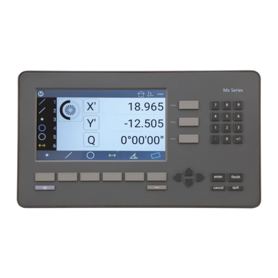
Mx200 Specifications Display: 7" Color 1024 X 600 LCD, with an LED backlit capacitive touch screen. Power: Power supply(included): 100-240VAC, 50/60Hz, 3.0A. Power Input to Mx200: 12V. Agency Approvals: CE DRO Dimensions: 286mm wide x 51mm deep x 162 mm high DRO Baseplate Dimensions: 120mm wide x 125mm deep x 9.5mm high... - Page 5 Using a 3MM Allen wrench and the supplied M6 screw, connect the riser block to the opening on the rear panel of the Mx200. The hole spacing is 38MM with a ¼”-20 thread pattern. Screws required to connect the OEM mount to the machine mount are not included in the Mx200 mounting kit.
- Page 6 • Complete the Mx200 readout installation according to the recommended mounting technique for the measuring system being used. • For standard “benchtop” installations place the Mx200 readout on a flat stable surface within reasonable operating distance from the measuring system.
- Page 7 C. Encoder connections: The Mx200 is designed to accept input from 1, 2, or 3 analog or TTL encoders. These encoders are typically arranged according to the major axis of the measuring system in which they are mounted; X, Y, and Z(or Q Rotary/Protractor).
- Page 8 D. Optical Edge Cables Optical Comparator Systems can be equipped with or without Optical Edge Sensor capability. The Mx200 is available either with or without the required electronics to support these sensors. This can be determined by inspecting the rear panel of the readout chassis and checking whether the (2) fiber optic terminals are present.
- Page 9 A. USB and RS232 Port Connections • The Mx200 is equipped with both a USB port and a 9 pin general purpose IO port to support data transfer to external storage drives, and PC systems(RS232). These connections will be described later in this document within the setup sections for Printing, and Data and Settings...
-
Page 10: Mx200 Software Setup
Mx200 Software Setup The following section will describe the basic setup parameters for configuring the Mx200. Not all setup screen items will be addressed in this section. Additional setup screen settings and procedures will be described in Section 4, “Additional Setup Screens”. - Page 11 Power Key for Power Off. Soft Keys(1-6) Executes the softkey button commands/selection displayed above the key. DRO Keys Execute X/Y/Z/Q zerroing funciton. Select functions as vertical softkeys. Menu Button Displays or advances the Softkey Menu. Long press to enter Mx200 Setup.
- Page 12 ENTERING SETUP: Enter the Mx200 Information and Setup Screens by pressing either the touchscreen “Mx” button in the top left corner of the screen, or by pressing the “Menu Button” and then choosing the “Mx” softkey button. Once in the Information screen, the first menu item called “Setup” will grant access to the setup menu items.
-
Page 13: Supervisor Password Protection
Press to Exit the Mx200 Readout Application. Supervisor Password Protection IMPORTANT: Many of the settings configured in the Mx200 require password authentication in order to modify them. In general, settings relating to the initial configuration and calibration of the readout will be password protected. -
Page 14: The Setup Menu
“Right Arrow” key. A small message should appear indicating “user mode”. The Setup Menu Most setup parameters in the Mx200 are configured using screens and data entry fields accessed via the setup menu items. Highlighting a setup menu items and pressing “Enter” grants access to that menu items’... -
Page 15: System Settings Import/Export
System Settings Import/Export The Mx200 readout has the ability to Import or Export a System Settings file from an attached USB drive. This allows for quick and convenient loading of previously configured setup parameters to an un- configured Mx200 readout. This also allows backups of existing parameter sets to be stored for use on another device, or as a settings backup for the current device. - Page 16 Select the IN or MM softkey to specify the Unit type for the entered encoder Units resolution(specified above). Select the softkey for the encoder type you are interfacing to the Mx200. (Signal)Type -TTL/1VPP/11uA/Nikon/Mitutoyo Select the softkey that corresponds to the desired Interpolation Factor for your Analog encoder.
- Page 17 Mx200 readout is started. This position can be established by configuring either Single, or Dual Reference marks in the Encoder Setup Screen. When configured the operator will be prompted to cross...
-
Page 18: Optical Edge Sensor Setup And Calibration
Configure and verify the correct encoder resolution and count direction for all axes. Set the Reference Mark type correctly for each encoder being configured. • At the Main Mx200 Settings screen press the “Set Home Position” button located at softkey 1. • •... - Page 19 Adjusting reference fiber positioning Access the Optical Edge setup screen at; • Mx Button-->Setup-->Optical Edge Press soft key 2 to access the light level “Install” screen. • • Follow the instructions in the prompt, adjusting the position of the reference fiber in the machine lamphouse until the Screen Sensor Level and Reference Sensor Level are “nearly”...
- Page 20 • Follow the instructions displayed in the teach dialog, positioning your sensor in the light, the dark, and finally in the light again. • Once the teach is complete press the Done button to finish the edge sensor calibration procedure. The system should not be prepared to enter edge positions with the Auto Enter and Manual Edge probe mode.
-
Page 21: Display Resolution And Format
Setting Display Resolution and Format The Mx200’s default display resolution is .001 millimeters and .0001 inches. This display resolution value applies to both the current DRO position and to the coefficient results of measured and constructed features. - Page 22 Display Description formats menu Display Res for Inch Press Enter to specify the Display Resolution for Inch Units. Display Res for MM Press Enter to specify the Display Resolution for MM Units. Press Enter to specify the Display Resolution for Degrees Minutes Display Res for DMS Seconds(DMS) Units of measurement results.
-
Page 23: Error Correction
Error Correction Stage Error Correction can be entered into the Mx200 systems by two different methods. Either the error correction data is entered(imported) directly through the error correction interface, or the correction data is imported from an existing correction file. -
Page 24: Squareness Correction
LEC is entered into the Mx200 as 2 distinct values, “Standard” and “Observed”. The standard value is the nominal or certified length of the increment to be used from your calibration artifact, and the observed... - Page 25 SLEC is entered into the Mx200 as 2 distinct values, “Standard” and “Observed” for each segment being corrected. The standard value is the nominal or certified length of the segment from your calibration artifact, and the observed value is the actual measurement that the Mx200 produces from that particular segment.
- Page 26 NLEC data through the Mx200 programming system. In either case the NLEC correction is entered into the system by importing features from the feature list.
- Page 27 Delete the skew and circle features from the feature list, and then proceed to measure all of the grid features in serpentine order starting from the bottom left, as seen below; Start Using the Mx200 tolerancing screens, set the nominal(or certified) X and Y position for each • feature in your grid, starting with (0,0).
- Page 28 The Mx200 can also configured to guide the user in the creation of an NLEC program. To enable the NLEC Program Assist mode navigate to the NLEC correction setup page and press the “Generate program” menu item. Mx Button-->Setup-->Error corrections-->NLEC-->Generate program Enter the following information about your NLEC calibration program.
-
Page 29: Additional Setup Screens
Additional Setup Screens Additional Mx200 configuration can be completed using the setup items found in the setup screens described in this section. Additional Description Setup Menus Contains settings that format the look of the main measuring interface, in Desktop particular the settings to display or hide button functions from the toolbars. - Page 30 The measure feature buttons are an example of these. When the “Desktop” setting for a particular function is set to “Bottom” or “Both” it will be displayed in the Mx200’s “Extra Functions” menu. This menu can be displayed by pressing the Menu key once. Additional keypresses of the Menu button will cycle through the pages of the Extra Functions menu.
- Page 31 The Switch to Home Movement Threshold configures the number of encoder counts required to switch the readout view back to “Live DRO”. For cases where the view is switching without moving the stage intentionally the Threshold value should be increased. The Touchscreen Enable flag will enable or disable touchscreen functionality in the Mx200 readout.
-
Page 32: Locks
When enabled the “Enter” key will automatically start a measurement. As points are added to the measurement the Mx200 will actively determine the intended feature type, based on the positions of the points entered. Double press “Enter”, or press “Finish” to... -
Page 33: Printouts
The “Programs” settings screen contains settings that impact program playback in the Mx200. User Recorded Edge Mode Part programs in the Mx200 will automatically select the Manual Edge Probe for the first feature of playback. This is done as a convenience to help prevent unintentional entering of edge positions, while positioning your sensor to begin playback. -
Page 34: Quick Keys
Note: The Number Pad Quick Key loading of part programs will only be permitted while in the main DRO view. This is to prevent undesired calling of a program while using other Mx200 screen. While in the main DRO view press the number pad key associated with your program, it will be loaded and run. -
Page 35: Rs232
Note: The general purpose IO port on the Mx200 is used for both serial data transfer and button input. As such the wiring for the connection cable must be specific to the connection modes being used. Please see the signal assignment diagram at the end of this section for reference. -
Page 36: Sounds
SW1 Common 7 TRIG_3_IN 8 TRIG_2_OUT 9 TRIG_3_OUT Sounds The “Sound” settings screen contains setup parameter for the Mx200’s internal beeper mechanism. Sound Description Function Set to Yes or No using the corresponding sofkey to enable or disable the Enable Sound... -
Page 37: Tolerance
Keypress Beep Configures the beep length of the Mx200 beeper. Set to 50, 100, 150, or 200 Length milliseconds using the appropriate softkey. Long keypress beep Configures the long press beep length of the Mx200 beeper. Set to 50, 100, length 150, or 200 milliseconds using the appropriate softkey. - Page 38 This product is warranted against defects in workmanship, material and design for 18 months from date of manufacture, to the extent that METLOGIX will, at its sole option, repair or replace the product or any part thereof which is defective, provided, however, that this warranty shall not apply to products subjected to tampering or, abuse, or exposed to highly corrosive conditions.
- Page 39 If you obtained the Software and any required serial number(s) from MetLogix or one of its authorized licensees (resellers) and as long as you comply with the terms of this Agreement, MetLogix grants you a non-exclusive license to install and use the Software in a manner consistent with its design and Documentation and as further set forth below.
- Page 40 United States and other countries, and by international treaty provisions. Except as expressly stated herein, this Agreement does not grant you any intellectual property rights in the Software and all rights not expressly granted are reserved by MetLogix Incorporated.
- Page 41 (a) you also transfer (i) this agreement, (ii) the serial number(s), the Software affixed to medial provided by MetLogix or its authorized distributor, and all other software or hardware bundled, packaged, or pre-installed with the Software, including all copies, Updates, and Prior Versions (as defined in Section 5);...
- Page 42 Updates If the Software is an Update to a prior version of MetLogix software (the “Prior Version”), the following apply: Your use of this Update is conditional upon your retention of the Prior Version. Therefore, if you validly transfer this Update pursuant to Section 4.6, you must transfer the Prior Version along with it. If you wish to use this Update in addition to the Prior Version, you may only do so on the same computer on which you have installed and are using the Prior Version.
- Page 43 Agreement, which will remain valid and enforceable according to its terms. This Agreement may only be modified in writing, signed by an officer of MetLogix, Inc. The English version of this Agreement will be the version used when interpreting or construing this Agreement. This is the entire Agreement between MetLogix and you relating to the Software and it supersedes any prior representations, discussion, undertakings, communications, or advertising relating to the Software.
- Page 44 (12) months, upon ten (10) days’ prior notice to you, to inspect your records, systems, and facilities to verify that your use of any and all MetLogix software is in conformity with your valid licenses from MetLogix. For example, MetLogix has the right to those of your records useful to determine whether installations of the Software have, or have not, been serialized, and you shall provide such records to MetLogix promptly upon request by MetLogix.
Need help?
Do you have a question about the Mx200 and is the answer not in the manual?
Questions and answers