Table of Contents
Advertisement
Quick Links
INTRODUCTION
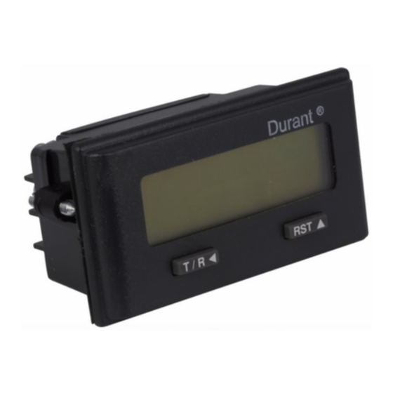
Your 5330X-403 is a counter with an eight-digit LCD
display. A programmable scaler and decimal point allow
for display in any engineering unit.
F ro nt View
Pla stic
fro nt p anel
sealed to
meet
NEM A 4X
Prog ramm ing
Bu tton
Rear View
7 + 10-30VD C
6 D C C omm on
Program
5 E nable/R
5 E nable/R
Ena ble
APPLICATIONS
Certain programming and wiring choices must be made to
accomplish your application. We recommend the follow-
ing sequence:
1.
Answer the following questions:
• What type of sensor will be used?
• To what engineering units should the counter be
scaled?
• How many pulses per item is the sensor
providing?
• Is a decimal point needed on the display?
2.
Calculate the scale factor.
MOUNTING
2.677" (67mm)
Recommended
Panel Cutout
®
Durant
PROGRAM MODE
To enter the program mode, a connection must be made
between terminals 1 and 5 (see page 4).
8-d ig it LCD
Display
Durant
®
RST
Reset/
Prog ramm ing
Bu tton
R eset Inpu t
R S T 4
Q u adrature A
IN A 3
Q u adrature B
IN B 2
G ro un d
G N D 1
1.299"
(33mm)
Gasket Installed?
Durant
Install mounting clip
Screens
There are four program-mode screens in the 5330X-403.
Upon entering the setup mode, the counter will display
screen 1. Press and hold the
pressing the
key to advance to successive screens.
Programming Screens
Screen
1
Count Scale Factor
2
Count Decimal Point
3
Reset to Offset Value
4
Reset Key Enable / Disable
OPERATION
Quadrature Counting
Quadrature is a bi-directional count mode requiring an in-
put signal at each of the totalizer's two count inputs. Quadra-
ture counting is typically accomplished by using a quadra-
ture encoder as the count source although any two sen-
sors with single channel outputs may be used if the sen-
sors are positioned correctly. In either case, both sensor
outputs must produce pulses at the same frequency and
there must be a phase shift between the signals. The total-
izer recognizes the phase shift and uses it to determine if
it should be counting up, or counting down. Finally, the
signal channels must alternate changes of state. This pro-
duces the four distinct input conditions from which the term
quadrature is derived. These conditions are off-off, on-off,
on-on, and off-on.
Quadrature Signal
Count Inputs
O ff
O n
O ff
O n
Count inputs A and B (terminals 3 and 2) are pulled down
to ground (terminal 1). The sensor must supply between
2.0 and 28 VDC at the count inputs for the totalizer to count.
The totalizer has high speed inputs only and is capable of
receiving pulses at 10kHz per channel if each signal is a
square wave and there is a 90° phase shift between the
two signals. For this reason, it is recommended that solid
state sensors (PNP output or NPN output with a pull-up
resistor) be used.
If the totalizer counts in the "wrong" direction at startup,
stop the process and switch the wires at terminals 2 and 3.
This will cause the totalizer to count in the "right" direction
when the process is re-started.
1
key while repeatedly
Function
Advertisement
Table of Contents

Related Manuals for Eaton Durant Courier 5330 403 Series


Summary of Contents for Eaton Durant Courier 5330 403 Series
- Page 1 Screens INTRODUCTION There are four program-mode screens in the 5330X-403. Your 5330X-403 is a counter with an eight-digit LCD Upon entering the setup mode, the counter will display display. A programmable scaler and decimal point allow for display in any engineering unit. screen 1.
- Page 2 COUNT SCALER Note: Pressing and holding the key will cause the Calculating the Count Scale Factor numbers to autoscroll. The count scale factor is used to convert the incoming count Next press the key to move the flashing digit one pulses to the desired unit of measure to be displayed (feet, place to the left.
- Page 3 Enabling the Front Panel Reset Key WIRING DIAGRAMS The fourth screen in the program mode allows the user to Solid State Quadrature Input enable or disable the front panel reset key. Current Sourcing Sensor R S T 4 7 + 1 0-3 0V D C IN A 3 6 D C C om m o n IN B 2...
- Page 4 Occupational Safety and Health Act of 1970, or FITNESS FOR PURPOSE. any regulations issued thereunder. In no event shall Eaton be liable for any loss, damages, fines, penalty or expense arising under BUYERS REMEDIES: Eaton’s obligations and liabilities under the said ACT.
- Page 5 Durant Products 901 S. 12th Street Watertown, WI 53094 800/540/9242 • 920-261-4070 Fax 920-261-9097 www.durant.com...
- Page 6 Durant Installation and Operation Manual Number 53300-903-04 Courier Models: 53300-403 Quadrature Indicator/Totalizer 53302-403 Quadrature Indicator/Totalizer w/Backlight 1.25" (31.75mm) 2.95" (74.93mm) 2.677" (68mm) Recommended 1.57" 1.299" Panel Cutout (39.87mm) (33mm) Durant® RESET POWER DC COMMON (Terminal 1) Internal battery: 3V, Lithium. COUNT INPUTS A &...
Need help?
Do you have a question about the Durant Courier 5330 403 Series and is the answer not in the manual?
Questions and answers