Table of Contents
Advertisement
Quick Links
UM1619
User manual
General purpose ST7540 power line modem module based on
ST7540 PLM and STM32 microcontroller
Introduction
This document explains how to use and setup the firmware and the software designed for
the STEVAL-IHP005V1 board and all the necessary setup for using the hardware.
The application firmware uses the ST7540 power line modem firmware stack driver
described in the UM1573: "ST7540 power line modem firmware stack", and is organized in a
layer structure. A dedicated layer allows the user to design his own application interfacing to
the module features with very simple and easy to use APIs. A dedicated software graphical
user interface (GUI) allows the user to use all the embedded features interfacing the PLM
module with the PC via an RS232 communication port.
This firmware is developed using STM32F10x Standard Peripherals Library Rel.3.5.0 and
IAR Embedded Workbench® IDE for STM32 microcontrollers Rel. 6.3
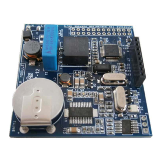
The STEVAL-IHP005V1 hardware module embeds an ARM 32-bit Cortex™-M3 core-based
STM32F103xB and a FSK power line transceiver ST7540.
Figure 1. STEVAL-IHP005V1
May 2013
DocID024383 Rev 1
1/56
www.st.com
Advertisement
Table of Contents

Related Manuals for STMicroelectronics STEVAL-IHP005V1


Summary of Contents for STMicroelectronics STEVAL-IHP005V1
- Page 1 Introduction This document explains how to use and setup the firmware and the software designed for the STEVAL-IHP005V1 board and all the necessary setup for using the hardware. The application firmware uses the ST7540 power line modem firmware stack driver described in the UM1573: “ST7540 power line modem firmware stack”, and is organized in a...
-
Page 2: Table Of Contents
Contents UM1619 Contents Features ........... 4 Hardware description . - Page 3 UM1619 Contents Appendix A Schematic diagrams and bill of material ..... 47 Bill of material ..........49 Appendix B CRC 16 calculation .
- Page 4 STEVAL-IHP005V1 block diagram ........
-
Page 5: Features
UM1619 Features Features • Configurable FSK power line modem interface with an embedded firmware stack for a complete power line communication management • 8 user configurable general purpose input/output pins • USART and SPI communication channel for module interfacing • Internal configurable RTC module with lithium backup battery •... -
Page 6: Hardware Description
The STEVAL-IHP005V1 is powered by a dual regulated DC power source, +12 VDC (pin 1) and +3.3 VDC (pin 2) from the power supply connector (J2). Pin 3 is the ground. -
Page 7: Figure 3. Three Phase Connection
UM1619 Hardware description It is possible to connect the module in a three phase line (in case of communication modules are connected in all three phases), in this case an external capacitor of 68nF X1 must be connected to any additional phase, and then the other side of capacitors together with the common pin 5 of the J1 connector, following the schematic shown in the Figure 3, and the 0-... -
Page 8: Figure 4. User Interface Connector
Hardware description UM1619 Figure 4. User interface connector A three-color LED allows the signaling of some module operations, such as data transmission and reception, programming phase, and so on. The user can also use these LEDs for his own application needs by means of dedicated APIs. Finally, a programming connector allows firmware download and debug, even if it is possible to use the remote firmware update feature to remotely update the firmware using the PLM, as described further in this user manual. -
Page 9: Getting Started
UM1619 Getting started Getting started System requirements In order to use the GP PLM module demonstration board with a Windows® operating system, a recent version such as Windows XP or Windows 7 must be installed on the PC. The version of the Windows OS installed on your PC may be determined by clicking on the “System”... -
Page 10: Figure 7. License Window
Figure 7. License window In the next window, click “Install”. In the following window, select the folder in which to install the software package. By default, the software is installed in the path: "C:\...\STMicroelectronics\ IHP005-V1. Figure 8. Destination folder window 10/56... -
Page 11: Figure 9. Installation Status Window
UM1619 Getting started after selecting the folder and clicking the “Next” button, installation of the software starts. Figure 9. Installation status window When installation is complete, click “Finish”. The GUI is located in the folder “Software - Remote Console 5.5”. DocID024383 Rev 1 11/56... -
Page 12: Hardware Installation
Hardware installation UM1619 Hardware installation Connect a regulated dual DC power supply to the power connector J2 or use the power source pins of connector J4 as described previously and power the module. In order to download the firmware, plug the programmer adapter (Figure 5) into the programming connector J3 and the IAR JLink programmer in the JTAG connector of the... -
Page 13: Figure 11. Gui Options Tab
UM1619 Hardware installation Figure 11. GUI options tab The module is now in programming mode; the “Programing mode” message will flash at the bottom of the interface, near the connected COM port indication. DocID024383 Rev 1 13/56... -
Page 14: Software Gui Description
Software GUI description UM1619 Software GUI description Introduction The software GUI is a demonstration tool that allows to program and set up the GP power line modules and test all the embedded features. The GUI is composed of several tabs, each one grouping different functions. A log window is present at the bottom of the GUI and is common to all tabs. -
Page 15: Figure 12. Gui Configuration Tab
UM1619 Software GUI description Figure 12. GUI configuration tab • Working Mode The working mode panel is used to specify the working mode of the power line communication. The communication between two or more modules can be with or without acknowledgment and with or without back acknowledgment. - Page 16 The description is stored in a local database, so if you run the GUI with a programmed node in another PC, the description is missing. The node list file is located in the directory C:\Program Data\STMicroelectronics\Remote Console\1.0.0.0\settings\donglelist.l...
-
Page 17: Dongle Tab
UM1619 Software GUI description If the module (dongle) is in programming mode, all the other tabs are locked. In order to unlock all the tabs, press the RUN button. The GUI and the module will enter in run mode, and the run mode message will appear in green at the bottom of the window. The module LED will be switched off. -
Page 18: Operations Tab
Software GUI description UM1619 Figure 13. GUI dongle tab As soon as the pin configuration is set by the user (checking or unchecking the corresponding check box), the SET IO CFG button must be pressed before the configuration has effect. After that, each output can be set/reset and each input can be checked. -
Page 19: Figure 14. Gui Operations Tab
UM1619 Software GUI description Figure 14. GUI operations tab If the message has to be sent in broadcast, the BROADCAST check box must be checked. As soon as the send message is sent, the green LED of the module connected to the GUI is switched on. -
Page 20: Program Tab
Software GUI description UM1619 Program tab The PROGRAM tab shown in Figure 15 is used to store permanently user data in the module flash memory. Actually is possible to store 20 bytes as example, but modifying a constant in the firmware (#define USER_SETTINGS_SIZE directive) in the interfaceconfig.h file it is possible to store more then 800 bytes of user data. -
Page 21: Service Tab
UM1619 Software GUI description Service tab The SERVICE tab is shown in Figure 16. This tab is dedicated to the test of all the special frames called service frames. The first button in the commands panel is the PING button. This is used to test if a module is connected to the power line, if it is working properly and if it is reachable. -
Page 22: Figure 17. Plm Communication Parameters Window
Software GUI description UM1619 Figure 17. PLM communication parameters window By default, the PLM is configured to work properly. Pressing the DEFAULT button, the parameter boxes are populated with the default values. Modify with care each parameter, and press the SET button to send the parameters to the addressed node (the selected node is shown in the top of the parameter window). -
Page 23: Sniffer Tab
UM1619 Software GUI description Sniffer tab It is possible to use the GUI interface to check the data transiting on the power line. This feature is useful when the PLM protocol parameters are tuned. By “sniffing” the transiting data it is easy to determine the overall performance of the network. Figure 18. -
Page 24: Figure 19. Sniffer Information
Software GUI description UM1619 The STOP button stops data acquisition without to losing previously sniffed data, appends new data as soon as the start button is pressed again. The CLEAR button deletes all the sniffed data from the sniffer main window, without deleting the sniffer file. Each time a data frame is sniffed, the log window is filled with some information concerning the sniffed frame as shown in the Figure... - Page 25 UM1619 Software GUI description As soon as the START button is pressed the sniffing date and time is shown. Each time a data frame is received this number represents the time passed (in seconds) after the previous received data frame. This symbol represents the frame type, and can be one of the following: –...
-
Page 26: Firmware Description
Firmware description UM1619 Firmware description Introduction The firmware structure is constituted of several layers, each managing a different feature. The application layer engine is the general interface between the user program and all the parts of the module. It manages the communication ports, the module peripherals such as RTC and I/Os, LEDs and timing management. -
Page 27: Figure 21. Memory Organization
UM1619 Firmware description this application is set to 60 Kbytes), plus 4 Kb of additional memory for a bootloader. Figure 21 shows the microcontroller memory organization. The bootloader is loaded at startup and checks the active segment containing the actual firmware. -
Page 28: Figure 22. Rfu Flow Chart
Firmware description UM1619 Figure 22. RFU flow chart 28/56 DocID024383 Rev 1... -
Page 29: Firmware Download
UM1619 Firmware description Firmware download In the setup directory there are different workspaces stored in different directories. In order to implement the remote firmware update feature it is necessary to download the project located in the workspace “Firmware - Application and Bootloader”. This workspace contains two different projects, one is the bootloader and the other one is the application itself. -
Page 30: Firmware Description
Firmware description UM1619 The setup folder contains also the Firmware - Bootloader folder, where inside there is the bootloader firmware; and the folder Firmware - Sniffer which contains the sniffer workspace to download in a PLM module useful if the data sniffing feature of the interface is used. In this case the PLM module will work only as a sniffer. - Page 31 UM1619 Firmware description At this level are available all the communication APIs and all the APIs for the application engine interfacing. In the main file, the following code is implemented for running the state machine engines: main(void) /* System initialization */ APP_ApplicationInit();...
-
Page 32: Firmware Data Types
Firmware description UM1619 Firmware data types The data type found in the application.h module, are listed below: /* USER FRAME STRUCTURE */ typedef struct APP_source_t source; APP_ftype_t type; bool broadcast; group; address; len; data[USER_PAYLOAD_SIZE]; /* MAX PAYLOAD SIZE: 100 bytes */ APP_ERROR_t error;... - Page 33 UM1619 Firmware description USER_DATA_BUSY, USER_DATA_IDLE }APP_userflag_t; /* PROGRAMMING COMMANDS */ typedef enum PROG_CMD_IDLE = 0x00, // No command PROG_CMD_ENTER_PROG_MODE = 0x01, // Enter the programming mode PROG_CMD_EXIT_PROG_MODE = 0x02, // Exit from programming mode PROG_CMD_SET_DATA = 0x03, // Write data into the internal flash PROG_CMD_GET_DATA = 0x04, // Get data from internal flash...
-
Page 34: Firmware Frame Types
Firmware description UM1619 The data type for the “dongle.h” module; “stm32f10x_gpio” module are listed hereafter: /* LED TYPE */ typedef enum A_LED_ERROR, A_LED_DATA, A_LED_BOTH }DH_LedType_t; /* LED STATUS */ typedef enum A_LED_ON, A_LED_OFF, A_LED_FLASH }DH_LedAction_t; /* PIN VALUE */ typedef enum Bit_RESET = 0, Bit_SET }BitAction;... -
Page 35: Ping Frames
UM1619 Firmware description 6.6.2 Ping Frames This particular frame is used to ping a remote (via PLM interface) or a local (via COMM interface) module. When a ping frame is received, this is managed directly at data link layer and is not notified at the application and consequently at the user levels. From the COMM interface module (SPI, USART, USB, etc.) buffer[0] = 10;... -
Page 36: Acknowledgment Frames
Firmware description UM1619 6.6.4 Acknowledgment Frames These frames are particular data frames sent to an external device connected to the COMM module, not allowed to be sent via PLM. They are used by the GUI interface to acknowledge the commands sent to the module. From the COMM interface module (SPI, USART, USB, etc.) uint8_t *buffer;... - Page 37 UM1619 Firmware description 0x02 = PROG_CMD_EXIT_PROG_MODE 0x03 = PROG_CMD_SET_DATA 0x04 = PROG_CMD_GET_DATA 0x05 = PROG_CMD_CLEAR_DATA 0x06 = PROG_CMD_DEVICE_BLANK 1) Enter in programming mode uint8_t *buffer; buffer[0] = 11; buffer[1] = APP_PROGRAMMING_FRAME; buffer[2,3] = target_module.group; buffer[4,5,6,7] = target_module.address; buffer[8] = CMD_ENTER_PROG_MODE; buffer[9,10] = CRC16;...
- Page 38 Firmware description UM1619 buffer[9] = PROG_GRP_LL_STACK_PARAM; buffer[10,11] = new_group; buffer[12,13,14,15] = new_address; buffer[16] = (uint8_t)module_working_mode; buffer[17] = hop_level; /* IF AES ENCRYPTION IS ENABLED */ buffer[18 -> 33] = *AES_key_buffer; // AES Key 0 to 15, 16 bytes buffer[34,35] = CRC16; /* IF AES ENCRYPTION IS DISABLED */ buffer[18,19] = CRC16;...
- Page 39 UM1619 Firmware description frame.data[0] = PROG_CMD_GET_DATA; // Command echo frame.data[1] = PROG_GRP_LL_STACK_PARAM; // Sub command echo frame.data[2,3] = PLM_MIN_SLOT; // Minimum backoff time frame.data[4,5] = PLM_MAX_SLOT; // Maximum backoff time frame.data[6,7] = PLM_NTW_P_GLOBAL_TX_TO; // Timeout for global tx frame.data[8,9,10,11] = PLM_NTW_P_BC_GLOBAL_TX_TO; // Timeout for broadcast frame retransmission frame.data[12,13] = PLM_NTW_P_ACTIVITY_TO;...
-
Page 40: Programming Frames
Firmware description UM1619 6.6.6 Programming Frames The programming frames are frames containing service commands concerning both some native module features (internal clock, general purpose inputs and outputs, etc.) and user defined service frames. Native frames are managed directly by the application engine. From the COMM interface module (SPI, USART, USB, etc.) uint8_t *buffer;... - Page 41 UM1619 Firmware description 2) Set module parameters: data link stack parameters uint8_t *buffer; buffer[0] = 62; buffer[1] = APP_SERVICE_FRAME; buffer[2,3] = target_module.group; buffer[4,5,6,7] = target_module.address; buffer[8] = SERVICE_PARAM_SET; buffer[9] = PROG_GRP_LL_STACK_PARAM; /* STACK PARAMETERS */ buffer[10,11] = PLM_MIN_SLOT; // Minimum backoff time buffer[12,13] = PLM_MAX_SLOT;...
- Page 42 Firmware description UM1619 4) Set module parameters: programming user parameters uint8_t *buffer; buffer[0] = 32; buffer[1] = APP_SERVICE_FRAME; buffer[2,3] = target_module.group; buffer[4,5,6,7] = target_module.address; buffer[8] = SERVICE_PARAM_SET; buffer[9] = PROG_GRP_USER_DATA; buffer[10 -> 29] = *user_data_buffer; buffer[30,31] = CRC16; 5) Get module parameters uint8_t *buffer;...
- Page 43 UM1619 Firmware description frame.broadcast = FALSE; frame.group = sender.group; // Device (the one been queried)group frame.address = sender.address; // Device (the one been queried)address frame.data[0] = SERVICE_PARAM_GET; // Command echo frame.data[1] = PROG_GRP_DEVICE_DATA; // Sub command echo frame.data[2,3] = sender.group; frame.data[4,5,6,7] = sender.address;...
- Page 44 Firmware description UM1619 buffer[4,5,6,7] = target_module.address; buffer[8] = SERVICE_INPUTS_GET; buffer[9,10] = CRC16; After a certain delay from the get command acknowledgment, the PLM module will send the following frame: APP_userdata_t frame; frame.source = SOURCE_PLM / ...; // Data source PLM, ... frame.type = APP_SERVICE_FRAME;...
- Page 45 UM1619 Firmware description After a certain delay from the get command acknowledgment, the PLM module will send the following frame: APP_userdata_t frame; frame.source = SOURCE_PLM / ...; // Data source PLM, ... frame.type = APP_SERVICE_FRAME; frame.len = 5; frame.error = APP_ERROR_NONE; frame.broadcast = FALSE;...
-
Page 46: Embedded Module Features Apis
Firmware description UM1619 6.6.7 Embedded module features APIs The PLM module has some embedded features which can be used by the user, some other are instead managed directly by the application engine. /* General purpose input pins status get */ uint8_t DH_GetInputs(void) /* General purpose global output pins value change (bit x = 1 ->... -
Page 47: Appendix A Schematic Diagrams And Bill Of Material
UM1619 Schematic diagrams and bill of material Appendix A Schematic diagrams and bill of material Figure 25. Schematic diagrams (1 of 3) DocID024383 Rev 1 47/56... -
Page 48: Figure 26. Schematic Diagrams (2 Of 3)
Schematic diagrams and bill of material UM1619 Figure 26. Schematic diagrams (2 of 3) 48/56 DocID024383 Rev 1... -
Page 49: Bill Of Material
UM1619 Schematic diagrams and bill of material Figure 27. Schematic diagrams (3 of 3) Bill of material Table 1. Bill of material Voltage / Technology Ref. Part / value Tol. % Watts Manufact. current information Lithium battery Through BATT1 BR2032 Panasonic hole 190mAh... - Page 50 Schematic diagrams and bill of material UM1619 Table 1. Bill of material (continued) Voltage / Technology Ref. Part / value Tol. % Watts Manufact. current information COG ceramic C6,C7 33 pF 50 Vdc SMD 0603 capacitor C8,C12,C13, C14, C15,C18,C2 X7R ceramic 100 nF 50 V SMD 0603...
- Page 51 UM1619 Schematic diagrams and bill of material Table 1. Bill of material (continued) Voltage / Technology Ref. Part / value Tol. % Watts Manufact. current information 220 uH 0.24 A Power inductor EPCOS PNP small signal Q1,Q2 BC857 transistor SOT23 0R-NM Not mounted SMD 1206...
- Page 52 Schematic diagrams and bill of material UM1619 Table 1. Bill of material (continued) Voltage / Technology Ref. Part / value Tol. % Watts Manufact. current information FSK power line ST7540 transceiver HTSSOP28 STM32F103 32-bit MCU CBT7TR LQFP48 3 to 5.5 V, low power, up to 400 ST3232CTR kbps RS-232...
-
Page 53: Appendix B Crc 16 Calculation
UM1619 CRC 16 calculation Appendix B CRC 16 calculation The CRC 16 is based on the X16 + X15 + X2 + 1 polynomial /* Used CRC 16 table */ const uint16_t TableCRC16[256] = { 0x0000, 0xC0C1, 0xC181, 0x0140, 0xC301, 0x03C0, 0x0280, 0xC241, 0xC601, 0x06C0, 0x0780, 0xC741, 0x0500, 0xC5C1, 0xC481, 0x0440, 0xCC01, 0x0CC0, 0x0D80, 0xCD41, 0x0F00, 0xCFC1, 0xCE81, 0x0E40, 0x0A00, 0xCAC1, 0xCB81, 0x0B40, 0xC901, 0x09C0, 0x0880, 0xC841,... -
Page 54: References
References UM1619 References UM1573 ARM-based 32-bit MCU STM32F10x Standard Peripheral Library Rel. 3.5.0 (2011) ST7540 FSK power line transceiver datasheets (2006) AN3046 IAR Embedded Workbench® IDE for STM32 microcontrollers Rel. 6.3 documentation (www.iar.com) 54/56 DocID024383 Rev 1... -
Page 55: Revision History
UM1619 Revision history Revision history Table 2. Document revision history Date Revision Changes 23-May-2013 Initial release. DocID024383 Rev 1 55/56... - Page 56 Please Read Carefully: Information in this document is provided solely in connection with ST products. STMicroelectronics NV and its subsidiaries (“ST”) reserve the right to make changes, corrections, modifications or improvements, to this document, and the products and services described herein at any time, without notice.
-
Page 57: Steval-Ihp005V1
Mouser Electronics Authorized Distributor Click to View Pricing, Inventory, Delivery & Lifecycle Information: STMicroelectronics STEVAL-IHP005V1...
Need help?
Do you have a question about the STEVAL-IHP005V1 and is the answer not in the manual?
Questions and answers