Table of Contents
Advertisement
Quick Links
Advertisement
Table of Contents

Related Manuals for ViTiny UM20-CSZ1236


Summary of Contents for ViTiny UM20-CSZ1236
- Page 1 UM20-CSZ1236 User’s Guide Version 1.0...
-
Page 3: Table Of Contents
Contents Product Introduction ......2 Packing Contents ......2 Assemble microscope with stand 2 IR Remote controller ....4 Microscope menu functions ..9 Microscope introduction: ..23 Microscope Focus ...... 26 Microscope accessory....30 Printed Notice ........31 Maintenance ......31 Product Specification .... -
Page 4: Product Introduction
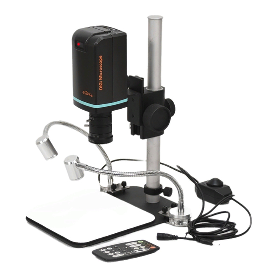
USB-C 3.0 Cable User’s Guide Power adaptor Calibrator S107 Stand CSZ1236 Lens Stand assemble guide Gooseneck Light Software download: http://www.vitiny.com/vitiny_en/ap_program.html 1.2 Assemble microscope with stand 1.2.1 Fix microscope Tighten the microscope onto stand○ . Refer to Stand assembling instruction for detailed explanation. - Page 5 ○ 1.2.2 Start to use microscope Connect the HDMI cable○ to HDMI monitor and adaptor○ to power. Microscope will turn on when Power in. ○ ○...
-
Page 6: Ir Remote Controller
1.2.3 Power On/Off Press Power to turn on microscope. Choose HDMI mode or Auto on HDMI monitor to output image. *Long press means press and hold the button for 2 seconds* 1.3 IR Remote controller The microscope operation and functions is controlled by the IR remote controller. - Page 7 :When preview on (4) Snapshot PCCam mode, press snapshot to take picture. (5) LED Adjustment: No function. (6) Motor Reset (Recalibrates entire operation):Returns to the lens position. If a loss of electricity occurred during operation, please reset the operation. (7) Manual focus :Zooms in;...
- Page 8 (9) Exposure Value: 20 levels of exposure value are selectable, from - 10~Auto~+9. :Use to increase exposure when the image (9-1) Increase is too dark. :Use to decrease exposure when the (9-2) Decrease image is too bright. :Open/close menu for setting. Refer to (10) Menu on Screen Section 1.4.
- Page 9 ○ ○ : Status bar show [FL] ○ (16) Status Bar for free lens. The area○ e tells the operation status and only show 3 seconds. (16-1) Area○ e : (16-2-1) OZ:Optical Zoom. Ex: OZ:500. 500means sensor position. (16-2-2) SZ:Step Zoom. Ex :SZ : 500. Same format as OZ. (16-2-3) AFS:Single Autofocus.
- Page 10 (16-2-5) EV:Exposure Value. Ex: EV: 5, means EV is +5, EV:-5 means EV is -5. (16-2-6) MR:Motor Reset. (16-2-7) SHA:Sharpness. Ex: SHA►SET(5), means sharpness is 5. SHA►SET(10) means the maximum 10. (16-2-8) FRZ:Image Freeze. Ex: FRZ►ON, means freeze image, FRZ►OFF means unfreeze image. (16-2-9) WB:White Balance Calibration.
-
Page 11: Microscope Menu Functions
(18) Image Freeze : ON/Off to freeze or unfreeze the image. (19) Sharpness : On/Off to set sharpness at Minimum and Maximum level. Microscope menu functions Press button to enter MENU, press Up and Down choose item, Left and Right to turn on/off or adjust parameter. - Page 12 1.4.1 EXPOSURE To set exposure time, see below: (1) Shutter: Digitally control amount of light, the amount is smaller the image is darker and the frame rate is also slower.
- Page 13 (2) AGC (Auto Gain Control) :auto control the brightness based on setting when light is not enough. (3) SENS-UP :Only available when item (2) AGC value is larger than 0, use to increase Senor to light’s sensibility. (4) Brightness: Adjust image brightness. (5) D-WDR: Digitally adjusting exposure in areas of the frame to maintain optimum detail in both the shadows and highlights of the image.
- Page 14 (6-1) POS/SIZE:Adjust de-fog position and area. (6-2) GRADATION: To set gradation levels near the edge of defog area. (6-3) DEFAULT: Return to Factory setting. (6-4) RETURN: Return to Last page or Save & End Menu. (7) RETURN: Return to Last page or Save & End Menu. 1.4.2 BACKLIGHT Press left/right button to choose turn on/off Backlight mode.
- Page 15 (2-1) LEVEL: To adjust brightness level. (2-2) AREA: Choose the back light compensation area and size. (2-3) DEFAULT: Return to default setting. (2-4) Return: Return to last page or Save & End Menu. (3) HSBLC (High Suppress Back Light Compensation) To identify the over luminance area by backlight, and proceed masking the area.
- Page 16 (4) WDR :Wide Dynamic Range. WDR allows an imaging system to correct the intense back light surrounding subject and thus enhances the ability to distinguish features and shapes on the subject. See below for setting WDR. (4-1) LEVEL: Adjust the WDR Level. (4-2) RETURN: Return to last page or Save &...
- Page 17 1.4.4 NR Noise Reduction:(NR) To obtain high quality output image and increase file compression. See below: (1) 2D NR:LOW/MIDDLE/HIGH, Edge Preserving 2D NR. (2) 3D NR LOW/MIDDLE/HIGH, Motion Adaptive 3D NR. (3) Return :Return to last page or Save & End Menu.
- Page 18 1.4.5 SPECIAL Set special functions: (1) D-EFFECT : Functions as following: Press Left or right to turn on or off. (1-1) FREEZE: Turn ON/OFF to freeze image. If Freeze function is turn on, the (1-2) Mirror function can not be used at the same time (1-2) MIRROR: Image rotatory.
- Page 19 MOTION: Detect the moving object, see below setting. (2-1) SELECT: Select the detected area. 4 areas are selectable. The selected area and sequence will change as MIRROR function is ON. (2-2) DISPLAY: Display the selected area. Position and area can be set in (2-1).
- Page 20 (2-6-1) VIEW TYPE: Select the frame type to show detected area. Frame type: transparent square, grid, both open or close all. (2-6-2) OSD VIEW: Select to show “MOTION DETECTED” when detect moving image. (2-6-3) TIME: Set Frame pausing time when detect the image is not moving .
- Page 21 (4-1) LIVE DPC: Dead Pixel Correction. Correct the live dead pixel during preview. (4-1-1) AGC LEVEL: Auto Gain Control. When light source is not enough, AGC will follow the threshold setting to adjust brightness and compensate the dead pixel. (4-1-2) LEVEL: Set the threshold value to judge if compensation is needed.
- Page 22 (4-2-1) POZ/SIZE: Choose the compensation area. (4-2-2) START: Start to do Static Dead Pixel correction. (4-2-3) DPC VIEW: Show corrected Dead Pixels. (4-2-4) LEVEL: Set the threshold value to judge if it needs to be corrected. (4-2-5) AGC: Auto Gain Control. When light source is not enough, AGC will follow the threshold setting to adjust brightness and compensate the dead pixel.
- Page 23 1.4.6 ADJUST Image Adjustment (1) SHARPNESS: Adjust Sharpness, higher value increases the higher contrast along/near edges of the image. (1-1) LEVEL: Adjust Image Sharpness level. (1-2) START AGC: Set start levels to adjust sharpness. (1-3) END AGC: Set end levels to end adjust sharpness. (1-4) RETURN: Return to last page or Save &...
- Page 24 (2) MONITOR: Adjust Monitor settings. (2-1) GAMMA: Adjust display contrast. (2-2) GLUE GAIN: Adjust Blue GAIN level. (2-3) RED GAIN: Adjust Red Gain level. (2-4) RETURN: Return to last page or Save & End Menu. (3) LSC:Lens Shading Correction. Use Lens shading correction to average the luminance of image.
-
Page 25: Microscope Introduction
Microscope introduction: 1.5.1 IR Remote Area/Indicator When both ○ and ○ LED indicator blinks, the microscope is in standby mode. Caution: Please remove the transparent protection sheet on the IR receiver area. ○ ○ ○ IR remote control aiming area○ The indicator will blink whenever buttons are pressed. - Page 26 If light blinks, means microscope is not connected to a PC 1.5.2 Power/USB/HDMI port Caution: Please hold the cable when remove from microscope and do not disassemble cables forcefully. ○ ○ ○ (1) Power○ Power adaptor is only compatible with the cord in :...
- Page 27 1.5.3 Stand gear box Assemble the stand and then screw the microscope onto the universal joint ○ on the gear box. ○...
-
Page 28: Microscope Focus
1.5.4 Illuminance :Insert the Gooseneck light clip into base Gooseneck Light○ near the pole, tighten the screws. Connect power○ with power adaptor. ○ ○ Microscope Focus The working distance of CSZ1236 lens can vary from 300mm to 20mm by using different stand as S-107, S-109 or S-110. At the fixed working distance, you are allowed to zoom in and out to change the magnification. - Page 29 (A) FAR/NEAR (B) Aperture (C) Focal length The function is as the following: (A) FAR/NEAR: Loose the screw and rotate toward FAR/NEAR side to focus the clear image. (B) Aperture F2.8~ F16 : The factory setting is “f/4” for general observation. If the image is blurry at the surrounding, recommend to decrease the aperture.
- Page 30 (C) Focal length 12 mm - 36 mm: At any working distance, you can adjust the 12-36 mm to change the magnification/ FOV. 12mm is the smallest magnification and the biggest FOV. On the contrary, 36 mm is the biggest magnification and the smallest FOV.
- Page 31 1.6.1 Magnification chart This Reference chart is measured base on 24” screen. CSZ1236 Zoom lens WD: 300mm~20mm on stand S107.S110. WD(mm) 300mm 200mm Aperture Focal length FOV(mm) 141.5 70.8 53.5 50.5 Mag(X) 4.8 5.9 7.5 12.2 WD(mm) 100mm 20mm Aperture Focal length FOV(mm) 37.5...
-
Page 32: Microscope Accessory
1.7 Microscope accessory 1.7.1 White balance card The white side is used to calibrate the white balance. If the object is tiny, place it onto the white balance card and move the card instead of the object. -
Page 33: Printed Notice
Printed Notice Please read the following information before operating. Maintenance Please abide by the following rules while storing or using this product: 2.1.1 Keep dry: do not place the product in a humid environment. Dry surroundings help extend the life of the product. 2.1.2 Avoid temperature shock: temperature shock (for example, taking the product into a warm room from a cold environment) will cause internal condensation inside the machine. -
Page 34: Product Specification
0.225A(Max) Consumption 68(L)×66(W)×169(H) mm Size Host weight around 339 grams Weight Temperature -5℃ ~ 35℃; Humidity-lower than 85% Operation Environment (No Condensation) For any changes, please visit http://www.vitiny.com *USB 3.0 transmission speed might be downgrade depends on the device/host condition... -
Page 35: Safety Instructions
Please remove the power supply from the microscope when not in use. Do not disassemble the machine for inspection. For any problems occurring in the machine itself, please power off the device and contact us through e-mail: mltc@vitiny.com... - Page 36 Service fees (including transportation fees) of product inspection. Repair fees. Fees of replaced parts ViTiny Service Center Tel: 07-657-9551 Fax: 07-657-9561 Address: 10 F., No.1, Section 1, Syuecheng Road, Dashu District, Kaohsiung City 840, Taiwan (R.O.C.) Website: http://www.vitiny.com...
- Page 38 ViTiny UM20-CSZ1236 Warranty Product Model no S/L nos. Purchase DD/MM/YYYY date Purchaser Tel no: Address Email Distributor Seal for Confirmation ( Stamp is necessary for validation of the Warranty ) ※Distributor’s seal shall include name of the shop, telephone and address※...
- Page 40 HTTP://WWW.VITINY.COM © MicroLinks Technology Corp. All rights reserved.
Need help?
Do you have a question about the UM20-CSZ1236 and is the answer not in the manual?
Questions and answers