Advertisement
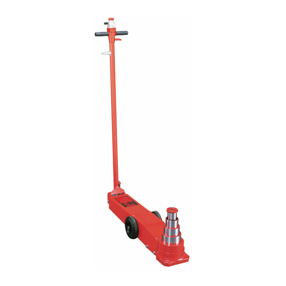
MODELS 72212 55/37/23/12 TON, 72214 63/49/27/14 TON, 72215 30/15 TON, 72218 33/20
TON, 72225 50/25 TON & 72244 44 TON CAPACITY AIR/HYDRAULIC FLOOR JACKS
SETUP • OPERATING • MAINTENANCE INSTRUCTIONS
Note: Revision letters (A, B, C, D etc.) after model numbers have been omitted as they do not affect the setup,
operating and maintenance instructions of a particular jack unless otherwise noted.
IMPORTANT: READ THESE INSTRUCTIONS BEFORE OPERATING
BEFORE USING THIS DEVICE, READ THIS MANUAL
COMPLETELY
AND
THOROUGHLY,
OPERATING
PROCEDURES,
MAINTENANCE REQUIREMENTS. FAILURE TO DO SO COULD
CAUSE ACCIDENTS RESULTING IN SERIOUS OR FATAL
PERSONAL INJURY AND/OR PROPERTY DAMAGE.
The use of portable automotive lifting devices is subject to certain
hazards that cannot be prevented by mechanical means, but
only by the exercise of intelligence, care, and common sense. It
is therefore essential to have owners and personnel involved in
the use and operation of equipment who are careful, competent,
trained, and qualified in the safe operation of the equipment and
its proper use. Examples of hazards are dropping, tipping, or
slipping of motor vehicles or their components caused primarily by
improperly securing loads, overloading, off-centered loads, use on
• Before lifting a vehicle, refer to the vehicle's service manual or
inquire from the vehicle manufacturer the recommended jack
lifting points and jack stand support surfaces on the vehicle
chassis.
• Inspect the jack before each use. Do not use the jack if it is
damaged, altered, modified, in poor condition, leaking hydraulic
fluid, or unstable due to loose hardware. Take corrective action
before using the jack.
• This jack was designed for lifting purposes only. Do not attempt to
work on the vehicle until jack stands rated equal to or greater than
the rated capacity of the jack are positioned to support the load.
1. Remove the two steel bushings that are tied to the bottom of
the handle.
2. Remove the hexagonal head bolts, washers and locknuts that
secure the bottom of the handle to the jack by way of a 1" steel
strap. The steel strap may be disgarded or used at a later time if
you wish to ship the jack to another destination.
3. Position the bottom of the handle so the handle legs straddle
the outside of the jack frame ears. Make sure the flexible spring
coming out of the jack is inserted in the bottom of the handle tube
and the air inlet fitting on the handle is facing toward the right of
the jack. The "right" of the jack can be determined when you are in
a position to read the jack warning label.
4. Align the handle leg holes with the jack frame ear holes and
install the steel bushings through the holes. Secure this assembly
with the bolts, washers and locknuts provided. A washer must be
placed under the head of each bolt and under the locknuts. Tighten
the locknuts enough to secure the handle but not too tight as to
hinder the pumping effort of the handle.
5. Install the quick disconnect air fitting of your choice to the air
inlet fitting on the handle.
PROFESSIONAL LIFTING EQUIPMENT
UNDERSTAND
SAFETY
WARNINGS AND
WARNING
®
other than hard level surfaces, and using equipment for a purpose
ITS
for which it was not designed.
It is the responsibility of the owner to make sure all personnel read
this manual prior to using this device. It is also the responsibility of
the device owner to keep this manual intact and in a convenient
location for all to see and read. If the manual is lost or not legible,
contact Norco Industries, Inc. for a free replacement. If the operator
is not fluent in English, the product and safety instructions shall be
read to and discussed with the operator in the operator's native
language by the purchaser/ owner or his designee, making sure
that the operator comprehends its contents.
This product is covered by a Limited Lifetime Warranty. For details
see the back cover of Norco's product catalog.
• Do not move or dolly the vehicle while on the jack.
• Do not use the jack beyond its rated capacity. Lift only dead
weight.
• Do not exceed 175 P.S.I. input air pressure.
• Center load on saddle. Be sure setup is stable. Off-center
loads can cause jack failure and/or loss of load.
• Use the jack on a hard level surface.
• Do not modify the jack or use saddle adapters or saddle
extenders unless approved or supplied by Norco.
• Always lower the jack slowly and carefully.
SETUP
6. Pull up on the red knob at the top of the handle so as to expose
a yellow line. This enables your jack to pump. Pushing the red
knob down prevents the pumping operation and can be used in
an emergency.
7. Install the extension holder on the handle six inches up from
the handle yoke with the hardware provided. Insert the extensions
in the holder.
8. Sometimes air gets trapped in the air/hydraulic systems of the
models 72212, 72214 and 72225 during shipment. An air bound
system feels spongy when pumped and sometimes the ram will
not rise.
PURGING AIR FROM THE HYDRAULIC SYSTEM
a. Pull the air control lever toward you while simultaneously
depressing the restart pin on the side of the jack chassis.
Hold this position for about 15 to 20 seconds.
b. Pull the air control lever toward you until the jack ram/s raise
to maximum height. If the condition remains, repeat steps
"a" and "b" until the air is purged from the system.
WARRANTY
Advertisement
Table of Contents

Related Manuals for Norco 72212


Summary of Contents for Norco 72212
- Page 1 ® PROFESSIONAL LIFTING EQUIPMENT MODELS 72212 55/37/23/12 TON, 72214 63/49/27/14 TON, 72215 30/15 TON, 72218 33/20 TON, 72225 50/25 TON & 72244 44 TON CAPACITY AIR/HYDRAULIC FLOOR JACKS SETUP • OPERATING • MAINTENANCE INSTRUCTIONS Note: Revision letters (A, B, C, D etc.) after model numbers have been omitted as they do not affect the setup, operating and maintenance instructions of a particular jack unless otherwise noted.
- Page 2 3. Become familiar with the capacity of each ram stage. For gently lower the vehicle onto support stands (jack stands). Make example, although the model 72212 has four ram stages and the sure the vehicle is safely supported by the safety support stands’...
Need help?
Do you have a question about the 72212 and is the answer not in the manual?
Questions and answers