
Related Manuals for Johnson Controls Zone Terminal


Summary of Contents for Johnson Controls Zone Terminal
-
Page 1: Table Of Contents
Theory of Operation Downloading Options Installation Procedures Tools Needed Physical Dimensions Environmental Information Connecting the Zone Terminal Installing the Inserts Positioning the ZT in the Controller Tower Physical Installation of Wall Mountings and Bases Connecting the ZT Troubleshooting Procedures Troubleshooting Chart Internal Diagnostic Errors ©... - Page 2 2 Zone Terminal...
-
Page 3: Lntroduction
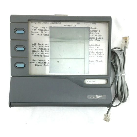
The Zone Terminal is used to monitor or adjust set points and for time Application Details scheduling of occupied, warmup/cooldown, or shutdown zone conditions. - Page 4 Panel Up/Down Arrow Keys E N T E R Door MAP1RT4 Figure 1: The Zone Terminal Keys Refer to Figure 1 to locate each of the seven ZT keys. Description Display Key 1, 2, 3 Moves the cursor through insert items...
- Page 5 AHU, UNT, or VAV controller with 24VAC transformer for Operation AS-ZTU100 Zone Terminal comes with a 6-pin telephone-style coiled cord. Also included are four inserts: one Time Schedule Overlay (remove the paper backing), and three clear inserts with set point labels (remove protective plastic backing).
- Page 6 Start HVAC PRO Select Zone Terminal From Main HVAC PRO Menu Select Configure ZT Files Define display files for single or multiple controllers. Define weekly schedules. Define holiday schedules. Define ZT Configuration Load File Press F2 and select up to three display files.
-
Page 7: Downloading Options
CAUTION: Any changes in the configuration of the AHU and UNT/VAV must be up-dated in the Zone Terminal. Failure to download the ZT after configuration changes to the AHU and UNT/VAV prevents access to the ZT Operating Modes. The following section presents options available for hardware connections Downloading necessary to complete the downloading process. - Page 8 ZT Download Failed, Strike 2 - Trying Again ZT Establishing Communication ZT error (18) -- Invalid or No response from ZT ZT Download Failed, Strike 3 - You’re Out Return Switch on CBLCON to Normal Position Press any key to Continue <Esc>Cancel <F7>View 8 Zone Terminal...
- Page 9 BINA RY OUT PUTS ANA OUT AS-CBLPRO-1 AS-CBLCON-0 6 6 6 DWNL ZONE TERMINAL LAPTOP Figure 4: Job Site Downloading With UNT/VAV Using AS-CBLCON-0 Notes: It is assumed that 24 VAC power has been applied to the controller. The AS-CBLCON-0 switch must be in the download position.
- Page 10 FMK. XFR100 or any 24VAC transformer 24 VAC, COM + Zone Bus 24 VAC AS-CBLPRO-1 Open Door Note: AHU102 Logic Board must be removed to download. ZONE TERMINAL DWNLD4 LAPTOP Figure 5: Job Site Downloading Without AS-CBLCON-0 10 Zone Terminal...
- Page 11 Splice here AS-CBLCON-0 Molex Connector AS-CBLPRO-1 Pin 3 = COM Pin 2=24 VAC 6 Pin RJ12 ZONE TERMINAL Phone Plug XFR-ZT Switch must be in Download position. Figure 6: Downloading Without an ASC Controller CAUTION: Connect only one transformer at a time into the AS-CBLCON-0.
- Page 12 12 Zone Terminal...
-
Page 13: Installation Procedures
51 mm). The Utility Mount Base with ZT measures 6.94 x 7.44 x 6.00 (176 x 189 x 152) when mounted on the AS-ENC100. Installation of the Zone Terminal must meet the following standards: Environmental Information Ambient operating conditions: 32 to 122°F (0 to 50°C) 10 to 90% non-condensing relative humidity 86°F (30°C) maximum dew point... -
Page 14: Connecting The Zone Terminal
1. Lay the ZT flat and press the white tab on the top of the ZT while pulling the front cover towards you. 2. Align the insert to the lower left front of the ZT. 3. Press the pieces back together. INSERT2 Figure 7: Template Installation 14 Zone Terminal... -
Page 15: Positioning The Zt In The Controller Tower
For optimum viewing, mount the ZT 65 inches from the floor to the top of Positioning the ZT the ZT unit. in the Controller Tower 65 inches from floor to top of Zone Terminal ZTTOWER Figure 8: ZT Mounted on Controller Tower Zone Terminal... -
Page 16: Physical Installation Of Wall Mountings And Bases
Attach the Enclosure Kit (AS-ENC100-0) to a flat surface or wall for Base Installation direct connection of the ZT to an Application Specific Controller. Pull wire through before attaching screws for the plastic base. MT&BASE Figure 10: Attaching the Enclosure Kit and Utility Mounting Base 16 Zone Terminal... - Page 17 For easy reading, mount the ZT at least 65 inches from the floor to the top of the ZT. Insert the telephone-type cord from the controller into the back of the ZT. WALMTZT Figure 12: Attaching ZT and Wall Mount Zone Terminal...
-
Page 18: Connecting The Zt
If ZT is connected 50 feet or less from the controller, install 24 AWG telephone cable between the controller and the ZT. If ZT is connected up to 500 feet from the controller, install 18 AWG wire. The ZT requires 24 VAC, Common, and Zone Bus. 18 Zone Terminal... - Page 19 AS-AHU101 Note: 24 VAC, COM, and Zone Bus wires of 18 AWG (500 ft. max.) must be connected between screw terminal strips. AS-FMK100 AS-RLY100 M100C TE-6100 UNT/VAV only CONECT2 Figure 14: Connecting the Zone Terminal Zone Terminal...
- Page 20 COM MON Connect TE-6100 here. ANALOG INPUTS BINARY IN BINARY OUTPUTS ANA OUT Connect VAV/UNT here. Switch must be in normal position. CONCT2J Connect ZT here. Figure 15: Connecting Remote ZT to UNT/VAV With AS-CBLCON-0 and Zone Sensor 20 Zone Terminal...
- Page 21 The Zone Terminal can be connected directly to a VAV/UNT through a Zone Sensor without the use of the AS-CBLCON-0 (Figure 16). This is a portable application. Zone Terminal VAV/UNT O F F AS -UNT101-0 0- 10V DC A NA LOG...
- Page 22 22 Zone Terminal...
-
Page 23: Troubleshooting Procedures
** For Error 5—This is only a warning and indicates the battery-backed data, specifically Time Scheduling, has been lost. If you press Enter, the ZT loads the default time schedule and you may continue. Replace the battery at your earliest convenience. Use a Panasonic® lithium or Ray-O-Vac®—battery number BR2325. Zone Terminal... -
Page 24: Internal Diagnostic Errors
R am R O M T est T est E P R O M DIAGFAIL Figure 17: Internal Diagnostics Controls Group 507 E. Michigan Street P.O. Box 423 Rev. Level — Milwaukee, WI 53201 Printed in U.S.A. 24 Zone Terminal...
Need help?
Do you have a question about the Zone Terminal and is the answer not in the manual?
Questions and answers