Advertisement
Quick Links
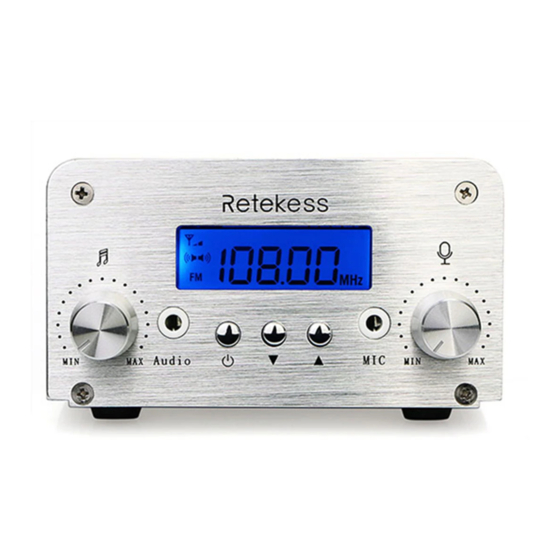
TR501
FM Transmitter User manual
Audio volume adjustment
Audio socket
ON/OFF setting button
Down button
Up button
Microphone socket
Microphone volume adjustment
Turn on and turn off the transmitter
In standby mode, long press
button, the transmitter goes into
working mode.
In working mode, long press
button, the transmitter goes into
standby mode.
Frequency setting
Short press
button to make
icon flashes.
Short press
button or
button, the frequency will step by
100k.
Long press
button or
button, the frequency will step by
100k continuously.
Transmitter power rate set and stereo mode switch
Transmitter power setting: short press
flashes. Press
button to decrease power rate. Press
to increase power. (2-grid signal icon indicates 6W, 1-grid signal icon
indicates 1W) Stereo mode switch: short press
icon flashes. Press
or
button to switch sound track.
1
Volume setting
Turn the audio knob or MIC knob clockwise to increase volume and
counter clock wise to decrease volume.
Specification
No.
01
02
03
04
05
06
07
08
09
10
11
12
13
14
15
16
17
Cautions
Do not turn on the transmitter before antenna connected.
Do not touch the antenna when the transmitter is power on.
Do not use the transmitter in explosive environment, such as gas
station and oil warehouse.
Thundering and lighting protection measurement should be taken.
Please comply with national laws and local radio regulations.
Maintenance of the transmitter can only be operated by professional
technicians.
76-108MHz frequency & Antenna length table
MHZ
button to make
icon
button
button to make
Index
Specification
Work voltage
DC12V
Work currency
< 3A
Frequency
76-108mhz
Frequency Stability
± 10PPM
Frequency step
100KHz
Work temperature
-10℃~45℃
Output impedance
50Ω
Transmit Output power rate
6W/1W
Harmonic wave
≤ -50dB
THD
0.30%
Frequency response
50Hz~15000Hz
Separation
≥ 30dB
Input level
≤ -15~15dBV
Modulation frequency offset
± 75KHZ
SNR
≥ 60dB
Transmitter size
144*100*54mm
Transmitter weight
550G
2
Transmit Frequency
76
78
80
82
84
MHZ
Antenna Length
38.6
37.8
36.6
35.8
35.0
IN
Transmit Frequency
94
96
98
100
102
MHZ
Antenna Length
31.1
30.3
29.9
29.5
28.7
IN
Guarantee
Remarks:
1. This guarantee card should be kept by the user, no replacement if
lost.
2. Most new products carry a two-year manufacturer's warranty from
the date of purchase. Further details, pls read www.retekess.com
3. The user can get warranty and after-sales service as below:
• Contact the seller where you buy.
• Products Repaired by Our Local Repair Center.
4. For warranty service, you will need to provide a receipt proof of
purchase from the actual seller for verification.
Exclusions from Warranty Coverage:
1. To any product damaged by accident.
2. In the event of misuse or abuse of the product or as a result of
unauthorized alterations or repairs.
3. If the serial number has been altered, defaced, or removed.
Guarantee
Model Number:
Serial Number:
Purchasing Date:
Dealer:
Telephone:
User's Name:
Telephone:
Country:
Address:
Post Code:
Email:
3
86
88
90
92
34.3
33.5
32.7
31.9
104
106
108
28.3
27.6
27.2
Advertisement

Related Manuals for Retekess TR501


Summary of Contents for Retekess TR501
- Page 1 ± 10PPM 2. Most new products carry a two-year manufacturer’s warranty from Frequency step 100KHz the date of purchase. Further details, pls read www.retekess.com Work temperature -10℃~45℃ 3. The user can get warranty and after-sales service as below: Output impedance 50Ω...
- Page 2 • When the transceiver is used for long transmissions, the Your Retekess radio is designed and tested to comply with a number In terms of measuring RF energy for compliance with these exposure radiator and chassis will become hot.
Need help?
Do you have a question about the TR501 and is the answer not in the manual?
Questions and answers