Advertisement
Quick Links
Assembly Instructions
FOR EVAPCO AUTHORIZED PARTS AND SERVICE, CONTACT YOUR LOCAL
MR. GOODTOWER SERVICE PROVIDER OR THE EVAPCO PLANT NEAREST YOU.
EVAPCO, INC. (World Headquarters) P.O. Box 1300, Westminster, Maryland 21158 USA
EVAPCO Europe
Industrieterrein Oost 4010
3700 Tongeren, Belgium
Phone: (32) 12 395029
Fax: (32) 12 238527
Email: evapco.europe@evapco.be
Rigging and
ESW CLOSED
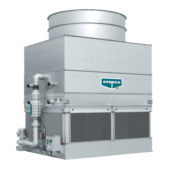
CIRCUIT COOLERS
EVAPCO products are manufactured worldwide:
Phone (410) 756-2600 Fax (410) 756-6450
EVAPCO Europe S.r.l.
Via Ciro Menotti 10
20017 Passirana di Rho (MI), Italy
Phone: (39) 02 9399041
Fax: (39) 02 93500840
Email: evapcoeurope@evapco.it
Bulletin 145-E Metric
EVAPCO Europe GmbH
Bovert 22
D-40670 Meerbusch, Germany
Phone: (49) 2159-6956-0
Fax: (49) 2159-6956-11
Email: info@evapco.de
Advertisement

Summary of Contents for EVAPCO ESW Series
- Page 1 FOR EVAPCO AUTHORIZED PARTS AND SERVICE, CONTACT YOUR LOCAL MR. GOODTOWER SERVICE PROVIDER OR THE EVAPCO PLANT NEAREST YOU. EVAPCO products are manufactured worldwide: EVAPCO, INC. (World Headquarters) P.O. Box 1300, Westminster, Maryland 21158 USA Phone (410) 756-2600 Fax (410) 756-6450 EVAPCO Europe EVAPCO Europe S.r.l.
- Page 2 ESW Closed Circuit Coolers Method of Shipment Rigging Bottom Section ESW models are shipped with the top section(s) separate from the bottom section(s). These sections have mating Lifting devices are located in the upper corners of the coil as flanges and will join together in a waterproof joint when shown in Figure 2.
- Page 3 ESW Closed Circuit Coolers Applying Sealer Tape Once the bottom section has been set on the supporting steel and bolted in place, the top flanges should be wiped down to remove any dirt or moisture. Sealer tape should be placed over the mounting hole centerline on the side flanges.
- Page 4 ESW Closed Circuit Coolers The preferred method for extended lifts is to use slings Extended Lifts under the unit (see Figures 5, 6, 7). Spreader bars should Important: The lifting devices and “U” bolts should be always be used between the cables at the top of the section used for final positioning only and for lifting where no to prevent damage to the upper flanges or fan cylinders.
- Page 5 ESW Closed Circuit Coolers There should be 3 wire clips on each side of the fan screen. Space the wire clips evenly across the Mounting Fan Screens radius of the fan screen as shown in Figure 11. 3,6 m Wide Models In certain situations some units may be shipped with the fan screens in the basin.
- Page 6 ESW Closed Circuit Coolers Optional Motor and Gear Box Davit This accessory is available to aid in the removal of fan motors and gear boxes. The assembly consists of a davit and a mounting base that is attached to the side of the unit next to the access door.
- Page 7 ESW Closed Circuit Coolers External Motor Installation 2,4 m Wide Models 1. Study Figure 15 before installing the motor base on the unit. 2. Insert the lifting device into “U” bolt A on motor base B. 3. Lift the motor base and insert the pivot pin C down into hole E and pivot pin F into hole D.
-
Page 8: Maintenance
Protective fan screens are provided across the top of the fan the cooler, leading to premature failure. cylinders of all models. Check and tighten all bolts. © 2007 EVAPCO, Inc. Bulletin 145-E Metric – 0707...


Need help?
Do you have a question about the ESW Series and is the answer not in the manual?
Questions and answers