Graco LP 555 Operation - Repair - Parts

Graco LP 555 Operation - Repair - Parts

Electric airless sprayer

Advertisement

Operation/Repair/Parts
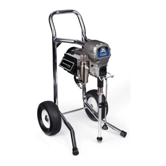
Electric Airless Sprayers
For professional use only.
Not approved for use in explosive atmospheres and hazardous locations.
For the application of architectural paints and coatings.
LP 555/655, S2550 Models:
3300 psi (22.7 MPa, 227 bar) Maximum Working Pressure
Important Safety Instructions
Read all warnings and instructions in this manual and in related manuals.
Be familiar with the controls and the proper usage of the equipment.
Save these instructions.
www.graco.com/techsupport
3A4203B
EN
ti29534a

Advertisement

Table of Contents
loading

Summary of Contents for Graco LP 555

  • Page 1 For professional use only. Not approved for use in explosive atmospheres and hazardous locations. For the application of architectural paints and coatings. LP 555/655, S2550 Models: 3300 psi (22.7 MPa, 227 bar) Maximum Working Pressure Important Safety Instructions Read all warnings and instructions in this manual and in related manuals.
  • Page 2: Table Of Contents

    Table of Contents Models ..........3 Warnings .
  • Page 3: Models

    Models Models Hi-Boy Lo-Boy Stand Model LP555 17M198 17M197 LP655 Schuko 17M201 17M200 S2550 17M215 LP555 17M208 17M209 LP655 17M211 S2550 17M220 3A4203B...
  • Page 4: Warnings

    Warnings Warnings The following warnings are for the setup, use, grounding, maintenance, and repair of this equipment. The exclamation point symbol alerts you to a general warning and the hazard symbols refer to procedure-specific risks. When these symbols appear in the body of this manual or on warning labels, refer back to these Warnings.
  • Page 5 • Check hoses and parts for signs of damage. Replace any damaged hoses or parts. • This system is capable of producing 3300 psi. Use Graco replacement parts or accessories that are rated a minimum of 3300 psi. • Always engage the trigger lock when not spraying. Verify the trigger lock is functioning properly.
  • Page 6 Do not kink or over-bend the hose. • Do not expose the hose to temperatures or to pressures in excess of those specified by Graco. • Do not use the hose as a strength member to pull or lift the equipment.
  • Page 7 Warnings MOVING PARTS HAZARD Moving parts can pinch, cut, or amputate fingers and other body parts. • Keep clear of moving parts. • Do not operate equipment with protective guards or covers removed. • Pressurized equipment can start without warning. Before checking, moving, or servicing equipment, follow the Pressure Relief Procedure and disconnect all power sources.
  • Page 8: Component Identification

    Component Identification Component Identification Stand Models ti29535a Trigger Lock ON/OFF Switch M Drain Tube Pressure Control Fluid Intake Two-Finger Trigger Conversion Kit Pump Prime Valve Fluid Outlet Tip Guard Power Cord Wrap Spray Tip Filter (inside manifold) Finger Guard / TSO Fill Point Airless Hose Model/Serial Tag (Not shown, located Power Cord...
  • Page 9: Lo-Boy Models

    Component Identification Lo-Boy Models ti29692a Trigger Lock ON/OFF Switch M Drain Tube Pressure Control Fluid Intake Two-Finger Trigger Conversion Kit Pump Prime Valve Fluid Outlet Tip Guard Filter (inside manifold) Spray Tip Finger Guard / TSO Fill Point Model/Serial Tag (Not shown, located Airless Hose on bottom of unit.) Power Cord...
  • Page 10: Hi-Boy Models

    Component Identification Hi-Boy Models ti29537a Trigger Lock ON/OFF Switch M Drain Tube Pressure Control Fluid Intake Two-Finger Trigger Conversion Kit Pump Prime Valve Fluid Outlet Tip Guard Filter Spray Tip Finger Guard / TSO Fill Point Pail Hook Airless Hose Model/Serial Tag (Not shown, located Power Cord on bottom of unit.)
  • Page 11: Grounding

    Grounding Grounding The equipment must be grounded to reduce the risk of static sparking and electric shock. An electric or static spark can cause fumes to ignite or explode. An improper ground can cause electric shock. A good ground provides an escape wire for the electric current.
  • Page 12: Pressure Relief Procedure

    Pressure Relief Procedure Pressure Relief Procedure Turn pressure control to lowest setting. Follow the Pressure Relief Disengage the trigger lock. Procedure whenever you see this symbol. This equipment stays pressurized until pressure is manually relieved. To help prevent serious injury from pressurized fluid, such as skin injection, splashed fluid and moving parts, follow the Pressure Relief Procedure whenever sprayer is...
  • Page 13: Trigger Lock

    Pressure Relief Procedure Trigger Lock Put drain tube in a pail. Turn prime valve down. Leave prime valve in down (drain) position until you are ready to spray Always engage the trigger lock when sprayer again. is stopped to prevent the gun from being triggered accidentally by hand or if dropped or bumped.
  • Page 14: Setup

    Setup Setup Use wrenches to tighten securely. Engage trigger lock. When unpacking sprayer for the first time or after long term storage perform setup procedure. When first setup is performed remove shipping plug from fluid outlet. Connect airless hose to fluid outlet. Use ti29455a wrenches to tighten securely.
  • Page 15 Setup When unpacking sprayer for the first Make certain ON/OFF switch is OFF. time remove packaging materials from inlet strainer. After long term storage check inlet strainer for clogs and debris. ti24586a Plug power supply cord into a properly grounded electrical outlet. ti24638b Fill throat packing nut with TSO to prevent premature packing wear.
  • Page 16 Setup 10. Turn prime valve down. 15. Turn prime valve horizontal. Disengage trigger lock. ti29641a 11. Place fluid intake with drain tube in grounded metal pail partially filled with flushing fluid. See Grounding, page 11. NOTE: New sprayers are shipped with storage fluid that must be flushed out with mineral spirits prior to using the sprayer.
  • Page 17: Startup

    Startup Startup Turn pressure control 1/2 turn to start motor. Allow paint to circulate through sprayer until paint flows out the drain tube. Perform Pressure Relief Procedure, page 12. Turn pressure control to lowest pressure. 15 s ti24645a Turn prime valve horizontal. Disengage trigger lock.
  • Page 18 Startup Hold gun against grounded metal waste pail. Trigger gun until paint appears. High-pressure spray is able to inject toxins into the body and cause serious bodily injury. Do not stop leaks with hand or rag. Inspect for leaks. If leaks occur, perform Pressure Relief Procedure, page 12, then tighten all fittings and repeat ti29650a...
  • Page 19: Operation

    Operation Operation Spray Tip Installation Spray Spray test pattern. Adjust pressure to eliminate heavy edges. To avoid serious injury from skin injection do not put your hand in front of the spray tip when installing or removing the spray tip and tip guard.
  • Page 20: Clear Tip Clog

    Operation Clear Tip Clog NOTE: If spray tip is difficult to rotate when turning to the unclog position, perform In the event that particles or debris clog the Pressure Relief Procedure, page 12, then spray tip, this sprayer is designed with a turn Prime/Spray valve to spray position and reversible spray tip that quickly and easily repeat step 1.
  • Page 21: Digital Display

    Operation Digital Display Press and hold display button to change pressure units (psi, bar, or MPa). Some models are equipped with a digital display. This section explains how to use this feature. Pressure Display 1. Perform Pressure Relief Procedure, page 12. ti29542a Plug sprayer into grounded outlet.
  • Page 22 Operation Sprayer model number is displayed To erase last error code, press and hold followed by Data Point 1 which is the unit display button. power on time in hours. Press display button again to display Data Point 4. The software revision is displayed.
  • Page 23: Cleanup

    Operation Cleanup Place fluid intake in flushing fluid. Use water for water base paint and mineral spirits for oil-based paint. Place drain Perform Pressure Relief Procedure, tube in waste pail. page 12. Remove tip guard and Spray Tip. For additional information, see separate gun manual.
  • Page 24 Operation Stop triggering gun. Move gun to waste Raise fluid intake above flushing fluid. pail, hold gun against pail, trigger gun to thoroughly flush system. While continuing to trigger gun, turn prime valve down. Then, release gun trigger. Allow flushing fluid to circulate until fluid comes out of drain tube clear.
  • Page 25 Operation 11. Engage trigger lock. 14. If flushing with water, flush again with mineral spirits or Pump Conditioner to leave a protective coating to prevent freezing or corrosion. ti29541a 12. Turn pressure control knob to the lowest pressure setting and turn ON/OFF switch to OFF position.
  • Page 26: Maintenance

    Maintenance Maintenance Routine maintenance is important to ensure proper operation of your sprayer. Maintenance includes performing routine actions which keep your sprayer in operation and prevents trouble in the future. Activity Interval Inspect/clean sprayer filter, fluid inlet strainer, and gun Daily or each time you spray filter.
  • Page 27: Troubleshooting

    Troubleshooting Troubleshooting Mechanical/Fluid Flow Follow Pressure Relief Procedure, Check all possible problems and causes page 13, before checking or repairing. before disassembling the unit. What to Check What to Do If check is OK, go to next When check is not OK, Problem check refer to this column...
  • Page 28 Troubleshooting What to Check What to Do If check is OK, go to next When check is not OK, Problem check refer to this column Pump output is low Pump rod damage. Repair pump. See pump manual. Low stall pressure. Turn pressure knob fully clockwise.
  • Page 29 Troubleshooting What to Check What to Do If check is OK, go to next When check is not OK, Problem check refer to this column Fluid is spitting from gun Air in pump or hose. Check and tighten all fluid connections.
  • Page 30 Troubleshooting Electrical View digital display or remove control box cover to view control board status light. To determine which code (or any Symptom: Sprayer does not run, stops other code besides voltage supply) refer running, or will not shut off. to the control board status light.
  • Page 31 Troubleshooting Problem What to Check How to check Check transducer or transducer Sprayer does not run at all Make sure there is no pressure in the system (see Pressure Relief connections Procedure, page 12). Check fluid Display shows E=02 path for clogs, such as clogged filter. Use airless paint spray hose with no metal braid.
  • Page 32 Troubleshooting Problem What to Check How to check Sprayer does not run at all Check voltage supply to the sprayer Turn ON/OFF switch OFF and (control board is detecting a multiple disconnect power to sprayer. voltage surges). Locate a good voltage supply to Display shows E=04 prevent damage to electronics.
  • Page 33 Troubleshooting Problem What to Check How to check 6.Connect the Red and Black leads from the motor to an Ohm meter. Rotate the motor while checking for opens. If an open is found replace the motor. BLACK (-) RED (+) YELLOW 1-3 ohms ti24723a...
  • Page 34 Troubleshooting Problem What to Check How to check 8.Use an Ohm meter to check motor for shorts. Connect (–) meter lead to motor case. Move the (+) meter lead to each motor wire. Meter should read open on all wires. GROUND BLACK YELLOW...
  • Page 35 Troubleshooting Problem What to Check How to check Basic electrical problems Motor leads are securely fastened Replace loose terminals; crimp to and properly mated leads. Be sure terminal are firmly connected. Clean circuit board terminals. Securely reconnect leads. For loose motor brush lead Tighten terminal screws.
  • Page 36 Troubleshooting Sprayer Will Not Run (See following page for steps) Remove Control box cover. Turn sprayer ON. Observe control board status light on See Step 1. Do you control board (see page 27). have over 100 VAC (220 VAC for 230v units)? No Light Once Normal Operation...
  • Page 37 Troubleshooting Step 1: Step 3: Plug Power cord in and turn Check motor thermal switch. switch ON. Connect probes Unplug yellow wires. Meter to L and N on control board. should read continuity. Turn meter to AC Volts. NOTE: Motor should be cool during reading.
  • Page 38 Troubleshooting Sprayer Will Not Shut Off Remove control box cover so the control board status light can be viewed Perform Pressure Relief Procedure, if available. page 12. Leave prime valve open (down) and turn ON/OFF switch OFF. Troubleshooting Procedure Plumb pressure gauge into paint hose, Mechanical problem: plug sprayer in, and turn power switch ON.
  • Page 39: Stand Sprayer Parts

    Stand Sprayer Parts Stand Sprayer Parts Models 17M197, 17M208 Ref. Torque 30-35 in-lb (3.4 - 4.0 N•m) ti29693a See page 51 3A4203B...
  • Page 40: Stand Sprayer Parts

    Stand Sprayer Parts Stand Sprayer Parts Models 17M197, 17M208 Ref. Torque 140-160 in-lb (15.8 - 18.1 N•m) 30-35 in-lb (3.4 - 4.0 N•m) Hammer tight 25-30 ft-lb (33.9 - 40.7 N•m) ti29548a 3A4203B...
  • Page 41 Stand Sprayer Parts Stand Sprayers Parts List Models 17M197, 17M208 Ref. Part Description Qty. Ref. Part Description Qty. LABEL, side 107434 BEARING, thrust MOTOR, includes 54a, 116073 WASHER, thrust 116074 WASHER, thrust 287015 110/120V 116079 BEARING, thrust 287060 230V 117501 SCREW, mach, hex 54a 118716 RING, retaining...
  • Page 42: Lo-Boy Sprayer Parts

    Lo-Boy Sprayer Parts Lo-Boy Sprayer Parts Models 17M201 Ref. Torque 140-160 in-lb (15.8 - 18.1 N•m) 30-35 in-lb (3.4 - 4.0 N•m) See page 51 ti29695a 3A4203B...
  • Page 43: Lo-Boy Sprayer Parts

    Lo-Boy Sprayer Parts Lo-Boy Sprayer Parts Models 17M201 Ref. Torque 140-160 in-lb (15.8 - 18.1 N•m) 30-35 in-lb (3.4 - 4.0 N•m) Hammer tight 25-30 ft-lb (33.9 - 40.7 N•m) ti29696a 3A4203B...
  • Page 44 Lo-Boy Sprayer Parts Lo-Boy Sprayers Parts List Models 17M201 Ref. Part Description Qty. Ref. Part Description Qty. 287060 MOTOR, 230V 107434 BEARING, thrust includes 54a, 54b 116073 WASHER, thrust 54a 118716 RING, retaining 116074 WASHER, thrust 54b 248189 FAN, motor, includes 116079 BEARING, thrust 117501...
  • Page 45: Hi-Boy Sprayer Parts

    Hi-Boy Sprayer Parts Hi-Boy Sprayer Parts 17M198, 17M200, 17M209, 17M211 Ref. Torque 30-35 in-lb (3.4 - 4.0 N•m) See page 51 ti29697a 3A4203B...
  • Page 46: Hi-Boy Sprayer Parts

    Hi-Boy Sprayer Parts Hi-Boy Sprayer Parts 17M198, 17M200, 17M209, 17M211 Ref. Torque 140-160 in-lb (15.8 - 18.1 N•m) 30-35 in-lb (3.4 - 4.0 N•m) Hammer tight 25-30 ft-lb (33.8 - 40.6 N•m) ti29698a 3A4203B...
  • Page 47 Hi-Boy Sprayer Parts Hi-Boy Sprayers Parts List 17M198, 17M200, 17M209, 17M211 Ref. Part Description Qty. Ref. Part Description Qty. MOTOR, includes 54a, 107434 BEARING, thrust 116073 WASHER, thrust 287015 110V 116074 WASHER, thrust 287060 230V 116079 BEARING, thrust 54a 118716 RING, retaining 117501 SCREW, mach, hex...
  • Page 48: Hi-Boy Sprayer Parts

    Hi-Boy Sprayer Parts Hi-Boy Sprayer Parts 17M215, 17M220 Ref. Torque 140-160 in-lb (15.8 - 18.1 N•m) 30-35 in-lb (3.4 - 4.0 N•m) 23-27 in-lb (2.6 - 3.1 N•m) See page 51 ti29699a 3A4203B...
  • Page 49: Hi-Boy Sprayer Parts

    Hi-Boy Sprayer Parts Hi-Boy Sprayer Parts 17M215, 17M220 Ref. Torque 140-160 in-lb (15.8 - 18.1 N•m) 30-35 in-lb (3.4 - 4.0 N•m) Hammer tight 25-30 ft-lb (33.8 - 40.6 N•m) ti29700a 3A4203B...
  • Page 50 Hi-Boy Sprayer Parts Hi-Boy Sprayers Parts List Models 17M215, 17M220 Ref. Part Description Qty. Ref. Part Description Qty. 54a 118716 RING, retaining 107434 BEARING, thrust 54b 248189 FAN, motor, includes 116073 WASHER, thrust 116074 WASHER, thrust 244240 HOSE, drain, includes 116079 BEARING, thrust 117501...
  • Page 51: Control Box

    Control Box Control Box Ref. Torque 140-160 in-lb (15.8 - 18.1 N•m) 30-35 in-lb (3.4 - 4.0 N•m) 20-25 in-lb (2.3 - 2.8 N•m) 37-43 ft-lb (50.2 - 58.3 N•m) 130-150 in-lb (14.7 - 16.9 N•m) ti29703a 3A4203B...
  • Page 52: Control Box Parts List

    Control Box Control Box Parts List Ref. Part Description Qty. Ref. Part Description Qty. 17D888 POTENTIOMETER, 117828 PACKING, o-ring assembly 111457 PACKING, o-ring 243222 TRANSDUCER, 111600 PIN, grooved pressure control, 277364 GASKET, seat, valve includes 3 115494 SCREW, mach, 117493 SCREW, mach, hex Phillips, pan hd washer hd...
  • Page 53: Wiring Diagrams

    Wiring Diagrams Wiring Diagrams 110/230V NOTICE Heat from inductor coil of filter board may destroy wire insulation that comes in contact with it. Exposed wires could cause shorts and component damage. Bundle and tie loose wires so none lay in contact with inductor coil on the filter board.
  • Page 54: Technical Specifications

    Technical Specifications Technical Specifications LP 555, 655/S2550 Metric Sprayer Maximum fluid working pressure 3300 psi 228 bar, 22.8 MPa Maximum Delivery (555/5150) 0.54 gpm 2.0 lpm Maximum Tip Size (555/5150) 0.023 0.023 Maximum Delivery (655/8150) 0.60 gpm 2.3 lpm Maximum Tip Size (655/8150) 0.025...
  • Page 55 Technical Specifications LP 555, 655/S2550 Metric @ 70 psi (0.48 MPa, 4.8 bar) Noise** (dBa) Sound pressure 90 dBa Sound power 100 dBa Materials of Construction Wetted materials on all models zinc- and nickel-plated carbon steel, nylon, stainless steel, PTFE, Acetal, leather, UHMWPE, aluminum, tungsten...
  • Page 56 All written and visual data contained in this document reflects the latest product information available at the time of publication. The manufacturer reserves the right to make changes at any time without notice. Original instructions. This manual contains English. MM 3A4203 Copyright 2016, All manufacturing locations are registered to ISO 9001.

This manual is also suitable for:

Lp 655S2550

Table of Contents