
Subscribe to Our Youtube Channel
Summary of Contents for GABOR DMSS-502
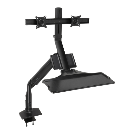
- Page 1 DMSS-502 DUAL MONITOR SIT-OR-STAND DESKTOP WORKSTATION User Manual for 17 to 27 in. Flat-Panel or Curved Screens...
-
Page 2: Safety Warnings
Thank you for choosing Gabor. The Gabor Dual-Monitor Sit-or-Stand Desktop Workstation can securely support two flat-panel or curved monitors from 17 to 27 inches. A sturdy two-section articulating arm offers control over swivel, tilt, rotation, and height for precise monitor and keyboard placement for sitting or standing while you work. -
Page 3: Product Specifications
Product Specifications Packaging Information ±10° Monitor display size Arm rotation Package weight ±180° 17 to 27 in. (43.2 to 68.6 cm) 28.9 lb. (13.1 kg) +10° Maximum weight per monitor Arm pivot Box dimensions 13.2 lb. (17.3 kg) ±90° 22.8 × 29.3 × 7.8 in. ±180°... - Page 4 Overview 1. Monitor bar (F) 17. Swivel set screw 2. Monitor bar locking knob 18. Lower cable guide 3. VESA plate (L) 19. Base (A) 4. VESA receiver 20. USB 3.0 ports 5. Monitor extension (G) 21. Bottom cable guide (H) 6.
- Page 5 Also Included Required tool Optional tool (grommet installation): Phillips Drill with 3/8 in. bit screwdriver M4 × 12 mm screws 3 mm hex key 4 mm hex key 6 mm hex key M5 × 12 mm screws M8 × 25 mm screws M6 ×...
-
Page 6: Assembling The Base
Assembling the Base Attaching to the Desk with the Clamp Sit the clamping plate (J) onto the tops of the Attach the flange (I) to the base (A) Make sure the flange (I) is flush clamp bolts (K). with the four hex screws (V). Make against the edge of the desktop. - Page 7 For Grommet (Non-edge) Desktop Installation Use the square holes on the plate (Q) as a template to mark Place the flat side of the Slide the clamping flanges where to predrill holes in the desktop. plate against the base, (S) and then the washers (Y) and use the four hex onto the bolts.
- Page 8 Attaching the Arm Insert the end of the arm marked with the + and – Lift the arm up to approximately a 45° angle. This will icons into the base’s receiver. make it easier to continue the assembly. You may need to rotate the arm back and forth in order to Use the hex key (N) to turn the swivel set screw on the back of completely insert it into the receiver.
- Page 9 Assembling the Accessory Slots, Keyboard, and Monitor Extensions Attaching the Accessory Slots Fit the accessory slots (C) onto the notch on Use the Phillips head screws (W) to secure The completed assembly should look like this: back of the keyboard extension (E), making the accessory slots to the keyboard sure the screw holes are aligned.
- Page 10 Assembling the Accessory Slots, Keyboard, and Monitor Extensions (cont.) Attaching the Keyboard Tray Remove the thumbscrew (E2) from the keyboard extension (E), Fit the bottom side of the Use the six Phillips head keyboard tray onto the top screws (U) to secure the and set it aside.
- Page 11 Assembling the Accessory Slots, Keyboard, and Monitor Extensions (cont.) Attaching the Monitor Extension Attach the monitor extension (G) The completed assembly will look like this: to the top of the keyboard extension. Use the two hex screws (T) to secure the monitor extension to the keyboard extension, and fasten with the hex key (P).
- Page 12 Attaching the Keyboard Extension to the Arm Fit the keyboard extension’s receiver onto the arm’s post. Press down and swivel the keyboard extension back and forth until it’s fully inserted. Use hex key (N) to tighten the set screw on the side of the keyboard extension’s receiver.
- Page 13 Attaching the Monitor Support Bar Remove the locking knob from Replace the locking knob, and the monitor bar (F), and slide the screw it in until secure. Tighten the monitor bar onto the monitor hex screws with the hex key (O). extension.
- Page 14 Attaching the VESA Plates to the Monitors Important! Before you attach the VESA plate, hand thread one of the screws (M-A or M-B) to determine which size is appropriate for your monitor. Place the VESA plate on the back of the monitor with the notched end facing the If the screw is bottom of the monitor.
- Page 15 Attaching the Monitors If needed, loosen the receiver’s side set screws until the end of the screw is flush with the inside of the receiver so they won’t obstruct the VESA plate. Slide the VESA plate of To secure the screens, each monitor onto the tighten the set screws VESA receiver.
- Page 16 Adjusting the Arm Tension Once the monitors are mounted onto the workstation, adjust the arm tension by using the hex key (P) to tighten the arm tension screw until the workstation supports the weight of the monitors, keyboard, and devices. When properly adjusted, the workstation should move effortlessly between sitting and standing position, and remain steady at any position while you work.
- Page 17 Monitor Orientation ±360° The VESA mounts rotate 360° and allow the monitors ±360° to be in landscape or portrait orientation. Turn the screen to the desired orientation angle, and slide the VESA receiver to adjust the horizontal distance between the monitors. If needed, adjust the set screws on the bottoms of the VESA receivers to horizontally level the screens.
- Page 18 Adjusting Monitor Height Adjust the height of the monitors so the top of your screens are at, or slightly below, eye level. Support the monitor bar with one hand, and loosen the locking knob. Adjust the bar to the desired height, and tighten the locking knob until secure.
-
Page 19: Adjusting The Keyboard Angle
Adjusting the Keyboard Angle Use the hex key (O) to turn the keyboard angle screw clockwise to raise the tray’s angle, or counterclockwise to lower the angle. - Page 20 Adjusting the Keyboard Angle (cont.) Screw in the keyboard thumbscrew (E2) to lock the keyboard position. Important! Loosen the thumbscrew before readjusting the keyboard angle.
-
Page 21: Making Cable Connections
Making Cable Connections Snap the top monitor cable guide (M) onto the back of the monitor extension. Attach the bottom cable guide (H) to the flange and deposit the hex keys for storage. Remove the cable guides from the bottom of the arm and the back of the base with a Phillips screwdriver. - Page 22 Making Cable Connections (cont.) Connect the monitor’s power and video cables. Press the cables into the side notches of the top monitor cable guide (M), and deposit the hex keys for storage. Run the monitor and keyboard cables through the upper and lower cable guides, then reattach the guides with a Phillips screwdriver.
- Page 23 Congratulations, your workstation is assembled! Take advantage of the many features it offers whether you’re sitting or standing at your desk.
- Page 24 To obtain warranty coverage, contact the Gabor Customer Service Department to obtain a return merchandise authorization (“RMA”) number, and return the defective product to Gabor along with the RMA number and proof of purchase. Shipment of the defective product is at the purchaser’s own risk and expense.
Need help?
Do you have a question about the DMSS-502 and is the answer not in the manual?
Questions and answers