Table of Contents
Advertisement
We advise you to read this manual carefully, as it contains all the instructions for maintaining
the appliance's aesthetic and functional qualities.
For further information on the product: www.smeg.com
Contents
ORIGINAL INSTRUCTIONS
4
4
8
8
8
8
9
10
11
11
12
12
13
14
16
17
18
19
20
23
30
30
31
33
36
38
38
41
46
49
50
3
Advertisement
Table of Contents

Related Manuals for Smeg SY62MX9


Summary of Contents for Smeg SY62MX9
-
Page 1: Table Of Contents
5.3 Positioning 5.4 Electrical connection 5.5 Instructions for the installer ORIGINAL INSTRUCTIONS We advise you to read this manual carefully, as it contains all the instructions for maintaining the appliance’s aesthetic and functional qualities. For further information on the product: www.smeg.com... -
Page 2: Instructions
Instructions 1 Instructions • Keep children under the age of 8 away from the appliance when it 1.1 General safety instructions is in use. • Cleaning and maintenance must Risk of personal injury not be carried out by • During use the appliance and its unsupervised children. - Page 3 Instructions • Do not insert pointed metal objects • Before any operation on the (cutlery or utensils) into the slots in appliance (installation, the appliance. maintenance, positioning or movement) always wear PPM. • Do not pour water directly on very hot trays.
- Page 4 Instructions • Racks and trays should be inserted • Do not cover the bottom of the as far as they will go into the side oven cavity with aluminium or tin guides. The mechanical safety foil sheets. locks that prevent them from being •...
- Page 5 Instructions • Do not use cleaning products • Have the gas connection containing chlorine, ammonia or performed by authorised staff. bleach on parts made of steel or • Installation using a hose must be that have metallic surface finishes carried out so that the length of (e.g.
-
Page 6: Manufacturer Liability
Instructions • Before installation, make sure that • tampering with any part of the the local distribution conditions appliance; (nature and pressure of the gas) • use of non-original spare parts. and the adjustment of the 1.3 This user manual appliance are compatible;... -
Page 7: Disposal
Instructions 1.6 Disposal • Deliver the appliance to the appropriate recycling centre for This appliance must be electrical and electronic disposed of separately from equipment waste, or return it to the other waste (Directives retailer when purchasing an 2002/95/EC, 2002/96/EC, equivalent product, on a one for 2003/108/EC). -
Page 8: How To Read The User Manual
Instructions 1.7 How to read the user manual This user manual uses the following reading conventions: Instructions General information on this user manual, on safety and final disposal. Description Description of the appliance and its accessories. Information on the use of the appliance and its accessories. -
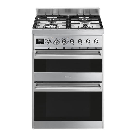
Page 9: Description
Description 2 Description 2.1 General Description 1 Upstand 4 Auxiliary oven light 2 Cooking hob 5 Auxiliary oven seal 3 Control panel 6 Auxiliary oven door 7 Multifunction oven light Rack/tray support frames 8 Multifunction oven seal 9 Multifunction oven door 10 Multifunction oven fan... -
Page 10: Cooking Hob
Description 2.2 Cooking hob AUX = Auxiliary burner UR2 = Ultra-rapid burner SR = Semi-rapid burner 2.3 Control panel 1 Programmer clock 3 Multifunction oven indicator light For displaying the current time, setting The indicator light comes on to indicate that programmed cooking operations and the the oven is heating up. -
Page 11: Other Parts
Description 4 Multifunction oven temperature knob 2.4 Other parts This knob allows you to select the cooking Shelves temperature and the Vapor Clean The appliance features shelves to position temperature. trays and racks at different heights. The Turn the knob clockwise to the required insertion heights are indicated from the value, between the minimum and maximum bottom upwards (see 2.1 General... -
Page 12: Available Accessories
Description 2.5 Available accessories Rack Tray rack Useful for supporting containers with food during cooking. To be placed over the top of the tray; for cooking foods which may drip. Rack Deep tray Useful for supporting containers with food during cooking. Useful for collecting fat from foods placed on the rack above and for cooking pies, Tray... - Page 13 Description Ring reducer Useful when using small cookware. WOK ring Useful when using a wok. The accessories intended to come into contact with food are made of materials that comply with the provisions of current legislation. Supplied and optional accessories can be requested to Authorised Assistance Centres.
-
Page 14: Use
3 Use High temperature inside the oven during use Instructions Danger of burns Improper use • Keep the oven door closed during Risk of damage to surfaces cooking. • Protect your hands wearing heat • Do not cover the bottom of the oven resistant gloves when moving food cavity with aluminium or tin foil sheets. -
Page 15: To Save Energy
Precautions First use 1. Remove any protective film from the A gas leak can cause an explosion. outside or inside of the appliance, If you smell gas or there are faults in the gas including accessories. system: 2. Remove any labels (apart from the •... -
Page 16: Using The Accessories
3.2 Using the accessories Racks and trays Racks and trays have to be inserted into the Ring reducers side guides until they come to a complete The ring reducers must be placed on the stop. hob grids. Make sure they are placed •... -
Page 17: Using The Hob
3.3 Using the hob Correct positioning of the flame- spreader crowns and burner caps All the appliance’s control and monitoring devices are located together on the front Before lighting the hob burners, make sure panel. The burner controlled by each knob that the flame-spreader crowns are is shown next to the knob. -
Page 18: Using The Ovens
3.4 Using the ovens Multifunction oven functions Switching on the multifunction oven Static As the heat comes from above and To switch on the multifunction oven: below at the same time, this system 1. Select the cooking function using the is particularly suitable for certain function knob. - Page 19 Fan assisted When using the ECO function, avoid opening the door during The operation of the fan, combined cooking. with traditional cooking, ensures consistent cooking even with complex recipes. Perfect for biscuits Cooking (and preheating) times and cakes, even when are longer with the ECO function.
- Page 20 General advice Auxiliary oven functions • Use a fan assisted function to achieve Static consistent cooking at several levels. As the heat comes from above and • It is not possible to shorten cooking times below at the same time, this system by increasing the temperature (the food is particularly suitable for certain could be overcooked on the outside and...
-
Page 21: Programmer Clock
• The temperature and the cooking time 3.5 Programmer clock depend on the quality and consistency of the dough. • When cooking on multiple levels, food should ideally be positioned on the second and fourth shelves; increase cooking time by a few minutes and only used fan functions. - Page 22 Timed cooking Setting the time Timed cooking is the function If the time is not set, the oven will which allows a cooking operation not switch on. to be started and then ended after a specific length of time set by the On the first use, or after a power failure, the user.
- Page 23 7. Press the clock key to reset the 4. Use the key to set the required minutes. (for example 1 hour) programmer clock. 5. Press the menu key . The text It is not possible to set a cooking time of more than 10 hours. will appear on the display in sequence with the pre-set cooking To cancel the set programming...
- Page 24 10. Return the function and temperature Minute minder timer knobs to 0. The minute minder timer does not 11. To turn off the buzzer just press any key stop the cooking operation but of the programmer clock. rather informs the user when the set time has run out.
- Page 25 Modifying the set data 1. Press the clock key 2. Use the value increase and value decrease keys to set the number of minutes required. Deleting the set data 1. Press the clock key 2. Hold down the value increase value decrease keys at the same time.
- Page 26 Multifunction oven cooking information table Weight Temperature Time Food Function Shelf (kg) (°C) (minutes) Lasagne 3 - 4 Static 220 - 230 45 - 50 Pasta bake 3 - 4 Static 220 - 230 45 - 50 Roasted veal Round 180 - 190 90 - 100 Pork loin...
- Page 27 Auxiliary oven cooking information table Weight Temperature Time Food Function Shelf (kg) (°C) (minutes) Lasagne 3 - 4 Static/Lower 220 - 230 50 - 60 Pasta bake Static/Lower 220 - 230 Pork chops Static/Lower 180 - 190 70 - 80 Sausages Grill 13 - 15...
-
Page 28: Cleaning And Maintenance
Cleaning and maintenance 4 Cleaning and maintenance Pour the product onto a damp cloth and wipe the surface, rinse thoroughly and dry with a soft cloth or a microfibre cloth. Instructions Food stains or residues Improper use Risk of damage to surfaces Do not use steel sponges and sharp scrapers, as they will damage the surfaces. -
Page 29: Cleaning The Doors
Cleaning and maintenance Flame-spreader crowns and burner caps The knobs should be cleaned with a soft cloth dampened with warm water, then For easier cleaning, the flame-spreader dried carefully. They can be removed by crowns and the burner caps can be pulling them out of their housing. - Page 30 Cleaning and maintenance To reassemble the door, put the hinges in 3. Remove the intermediate glass pane by the relevant slots on the front of the oven, lifting it upwards. making sure that the grooved sections A are resting completely in the slots. Lower the door and once it is in place remove the pins from the holes in the hinges.
-
Page 31: Cleaning The Oven Cavities
Cleaning and maintenance 6. Reposition the internal glass pane. Take Removing rack/tray support frames care to centre and insert the 4 pins into Removing the rack/tray support frames their housings in the oven door by enables the sides to be cleaned more applying slight pressure. - Page 32 Cleaning and maintenance Vapor Clean (multifunction oven only) Cleaning the roof of the oven Vapor Clean is an assisted High temperature inside the oven cleaning procedure which during use facilitates the removal of dirt. Danger of burns Thanks to this process, it is possible •...
- Page 33 Cleaning and maintenance • Spray a water and washing up liquid End of the Vapor Clean cycle solution inside the oven using a spray 4. Open the door and wipe away the less nozzle. Direct the spray against the side stubborn dirt with a microfibre cloth.
-
Page 34: Extraordinary Maintenance
Cleaning and maintenance 4.4 Extraordinary maintenance 4. Slide out and remove the lamp. Replacing the oven light bulb Live parts Danger of electrocution • Disconnect the appliance from the power supply. The oven is fitted with a 40W light Do not touch the halogen lamp bulb. - Page 35 Cleaning and maintenance Removing and installing the seal The oven does not heat up: • Fuse defective; check and, if necessary, To remove the seal: replace the switch. • Unhook the clips in the 4 corners then • The function knob has not been set: set pull the seal outwards.
-
Page 36: Installation
Installation 5 Installation General information Connection to the gas mains can be made 5.1 Gas connection (not valid for the using a continuous wall steel hose in compliance with the guidelines established by the standards in force. The appliance is For installation in the UK, please preset for natural gas G20 (2H) at a refer to the “Local specifications for... - Page 37 Installation Carefully screw the hose connector 3 to the Connection with a steel hose appliance’s gas connector 1 (½” thread Make the connection to the gas mains ISO 228-1), placing the seal 2 between using a continuous wall steel hose whose them.
- Page 38 Installation Connection to LPG Room ventilation The appliance should be installed in rooms Use a pressure regulator and make the connection on the gas cylinder following that have a permanent air supply in the guidelines set out in the standards in accordance with the standards in force.
-
Page 39: Adaptation To Different Types Of Gas
Installation 5.2 Adaptation to different types of In case of operation with other types of gas, the burner nozzles must be changed and the minimum flame adjusted on the gas taps. Replacing nozzles 1. Remove the grids, burner caps and flame-spreader crowns in order to access the burner cups. - Page 40 Installation Adjusting the minimum setting for LPG Tighten the screw located at the side of the cock rod clockwise all the way. Following adjustment to a gas other than the one originally set in the factory, replace the gas setting label on the appliance with the one corresponding to the new gas.
- Page 41 Installation Gas types and Countries Gas types IT GB-IE FR-BE DE AT NL ES PT SE RU DK PL HU 1 Natural gas G20 • • • • • • • • • • 20 mbar • G20/25 20/25 mbar 2 Natural gas G20 •...
- Page 42 Installation Burner and nozzle characteristics tables 1 Natural gas G20 - 20 mbar Rated heating capacity (kW) Nozzle diameter (1/100 mm) Pre-chamber (printed on nozzle) (F3) Reduced flow rate (W) 1400 2 Natural gas G20 - 25 mbar Rated heating capacity (kW) 1.10 Nozzle diameter (1/100 mm) Pre-chamber (printed on nozzle)
- Page 43 Installation 7 LPG G30/31 - 30/37 mbar Rated heating capacity (kW) Nozzle diameter (1/100 mm) Pre-chamber (printed on nozzle) Reduced flow rate (W) 1400 Rated flow rate G30 (g/h) Rated flow rate G31 (g/h) 8 LPG G30/31 - 37 mbar Rated heating capacity (kW) Nozzle diameter (1/100 mm) Pre-chamber (printed on nozzle)
-
Page 44: Positioning
Installation 5.3 Positioning Any wall units positioned above the worktop of the appliance must be at a Heavy appliance minimum distance of at least Y mm. If a Crushing hazard hood is installed above the hob, refer to the hood instruction manual to ensure the correct clearance is left. - Page 45 Installation Appliance overall dimensions 600 mm 600 mm B - Class 2 subclass 1 min. 150 mm (Built-in appliance) 900 - 915 mm 750 mm 450 mm 600 mm Minimum distance from side walls or other flammable material. Minimum cabinet width (=A). C - Class 2 subclass 1 (Built-in appliance) The appliance must be installed by...
- Page 46 Installation Dimensions of the appliance: locations of Positioning and levelling gas and electric connections (mm) Heavy appliance Risk of damage to the appliance • Insert the front feet first and then the rear ones. The appliance must sit level on the floor to ensure stability.
-
Page 47: Electrical Connection
Installation General information Check the grid characteristics against the data indicated on the plate. The identification plate bearing the technical data, serial number and brand name is visibly positioned on the appliance. Do not remove this plate for any reason. Perform the ground connection using a wire 4. -
Page 48: Instructions For The Installer
Installation 5.5 Instructions for the installer • 220-240 V 3~ • The plug must be accessible after installation. Do not bend or trap the power cable. • The appliance must be installed 4 x 1.5 mm² four-core cable. according to the installation diagrams. •...
Need help?
Do you have a question about the SY62MX9 and is the answer not in the manual?
Questions and answers