
Related Manuals for Alpine Spas Cedar Barrel Sauna


Summary of Contents for Alpine Spas Cedar Barrel Sauna
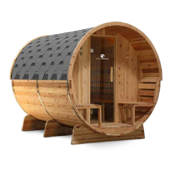
- Page 1 Cedar Barrel Sauna Assembly Manual Follow along build VIDEO available from our Alpine Spas support page: http://alpinespas.co.nz/support 0800 99 33 88 | service@alpinespas.co.nz | www.alpinespas.co.nz...
- Page 2 Pic of inside benches etc or sauna heater..
-
Page 3: Table Of Contents
CONTENTS Before You Start............................Location................................Oiling The Timber............................Electrics - Light............................Electrics - Heater............................Important Safety & General Information..................Safety & Operation............................Nature of Barrel Saunas..........................Warranty.................................. Pre-Assembly Checks..........................7-10 Parts List................................. Parts Labeled..............................Foundation................................Tools & Resources............................Installation Instructions........................... 11-26 Base................................... -
Page 4: Before You Start
PROCEEDING WITH INSTALLATION. INSTALLATION VIDEO AVAILABLE! Watch online - visit our support page at: http://alpinespas.co.nz/support LOCATION Think carefully about where you want to locate the sauna. After you have completed the installation the sauna won’t be able to be moved due to its size and weight. The sauna will need to be in a location that can have power access installed. - Page 5 THE FOLLOWING PARTS NEED TO BE OILED: Staves Front & Back Wall All of the staves need oil applied. Oil the Oil ONLY the exterior facing surfaces of exterior surfaces ONLY. the front and rear panels. The images below show the interior surface of these APPLY OIL (EXTERNAL SURFACE) panels which must be left unoiled.
-
Page 6: Electrics - Light
BEFORE YOU START ELECTRICS - LIGHT Equipment Lighting for the sauna is provided in the form of a sauna light-case and a light bulb, however no lighting cable or switch is provided as every setup location is different. The sauna light case meets ASNZS3000 electrical installation standard, is IPX4 rated and fully sealed. -
Page 7: Electrics - Heater
ELECTRICS - HEATER The provided sauna heater must be installed by a registered electrician. No wiring, switches, RCD or electrical accessories are included. Heater Model Sawo Sauna Heater 4.5kW - Model SCA-45NB. Setup Install the heater as per the manufacturer instructions included, along with any electrical protective devices . -
Page 8: Important Safety & General Information
IMPORTANT SAFETY & GENERAL INFORMATION PLEASE READ ENTIRE MANUAL THROUGH BEFORE PROCEEDING WITH INSTALLATION. SAFETY & OPERATION Read all health and safety instructions. If unsure about your health concerns, consult with your physician prior to use. If you feel light-headed or heat exhaustion during session, exit the sauna immediately. -
Page 9: Nature Of Barrel Saunas
OR SCAN QR CODE WITH SMART PHONE WOOD & EXPECTATIONS This Cedar Barrel Sauna is designed for outdoor use. The lumber is naturally resistant to the elements. Rain and sun will not damage the wood, although natural weathering and coloring of the wood will occur over time. -
Page 10: Pre-Assembly Checks
PRE-ASSEMBLY CHECKS PARTS LIST Installation Parts Label* Part Name Label* Part Name Inside Floor Panel Regular Staves Outside Floor Panel Starting Bottom Stave 2 (two sizes) Glass Door Final Top Stave Front Edge Capping Glass Door Hinges 2 Set Rear Edge Capping Door Handle, Magnet &... -
Page 11: Parts Labeled
PARTS LABELED NOTE: Appearance of sauna and particular parts may vary from the diagram shown above. -
Page 12: Foundation
PRE-ASSEMBLY CHECKS FOUNDATION Ensure the foundation can withstand the weight of the barrel sauna without subsiding. We recommend using either a concrete slab or a pile foundation. The base of the sauna must not rest upon anything that will degrade the quality of the timber (soil, grass etc.) Your foundation should have some form of drainage or contour, allowing storm water to drain away from the base of the sauna. -
Page 13: Tools & Resources
TOOLS Tools required include screw drivers set, power drill set, measuring tape, level, mallet, socket set. MALLET INCLUDED RESOURCES TIMBER WATERPROOF PROTECTION OIL SILICONE FOR BITUMEN ROOF OPTIONAL STAPLER ASSISTS WITH ATTACHING BITUMEN ROOFING... -
Page 14: Base
INSTALLATION INSTRUCTIONS Stand all three cradles bases, equal distance apart The double sided base support screw is used to matching the length of the four cradle support lengths. connect the end cradle base supports to the support Take some time to note the dowels at the ends of the lengths. - Page 15 Secure the cradle support lengths by placing the half There are four double ended screws for the end cradle moon steel washer, standard washer and nut on to each supports. Screw part A, with the broad screw thread, thread appearing in the pre-created hole on the side. into the end cradle so the bolt end (part B) is left Tighten the nut using a socket set.
-
Page 16: Bottom Section
INSTALLATION INSTRUCTIONS Start by locating the ‘bottom stave’. This stave should Next, screw the bottom stave into the cradle base be labeled but will have two vent holes pre-drilled. supports using 3x ‘4*40mm’ screws Fit the bottom stave into the centre of the cradle Note that there are no pre-drilled holes. bases using the provided dowels (the rear vent should sit close to the back cradle base and the front vent centered between the front and middle cradle bases). -
Page 17: Front And Back Panels
Lay out the ‘Back Panel Parts 1, 2 & 3’ flat on ground Secure the back panels together using 4x ‘5*70mm with the pre-installed bench supports right side up. Screws’ into the pre-drilled holes labeled below at the top and bottom of the panel. The vent hole identifies the bottom of the back panel. Pre-installed Outdoor Bench Supports Heater Power Cable Hole Vent Hole Measure the depth of the groove in the 13 staves you This measurement will be used to mark the indentation have secured. - Page 18 INSTALLATION INSTRUCTIONS Use 22x ‘4*40mm screws to fasten two of the ‘panel Layout pieces ‘Front Panel Parts 1, 2 & 3’. Notice there set securing pieces’ to the bottom and top of the back are bench supports both on the inside and the outside panel, applying the indent measurement (as per step of the panel. Do not fix together yet. 15) to set the position. Place the completed back panel assembly aside. ‘Panel set securing piece’ Light Hole Indentation measurement Top and bottom of...
-
Page 19: Front And Back Panels + Staves
Applying the indent measurement from step 14, screw Secure the front panel assembly together using the 2x remaining ‘Panel Set Securing Pieces’ onto the 3x ‘5*70mm Screws’ into the pre-drilled locations top and bottom of the front panel assembly using 22x marked (A) below. ‘4*40mm Screws’. Screw the door frame into the side panel using 2x ‘5*70mm Screws’ into the pre-drilled locations marked (B) below. - Page 20 INSTALLATION INSTRUCTIONS Install 16x more staves on either side of the barrel The remaining gap will be filled with the ‘Top Stave’ which is available in two smaller stave sizes. Due to but DO NOT fasten with screws yet. You may need natural swelling/shrinking of the cedar wood, one piece wiggle room to place the last stave - it is designed to is likely to fit better than the other.
-
Page 21: Steel Strap Connection
Familiarize yourself with the strap tightening systems With all three straps connected, align the back and and undo the assembly. Thread the assembly through centre straps up so that they cover the row of screws. the two steel strap ends to connect them together. The front strap will need to sit behind or forward of Attach a nut and washer on either side of the thread the screws if you are exiting the light cable through... -
Page 22: Glass Door
INSTALLATION INSTRUCTIONS Place the door’s hinges into the two grooves in the door Slot the two nodes of the door handle through the frame, and drill 3x ‘4*30mm’ flat head screws into each glass holes provided, use 2x’6*75mm screws to fix the hinge securing the door into place. handles together while squeezing both sides of the handles tight. You may need a block of something soft under the glass door to ensure it does not slip down. -
Page 23: Indoor Bench
Secure the outdoor bench seat into the bench supports Place the indoor bench seat inside, resting on the two using 4x ‘4*40mm’ screws. Screw down in between the pre-installed bench supports connected to the front gaps so the screw is hidden. and back panels. Secure with 4x ‘4*40mm’ screws into the bench supports, two screws on each end of the bench. -
Page 24: Outdoor Shelf
INSTALLATION INSTRUCTIONS Next, align the shelf with the towel rack at the same Place the outside floor panel in front of the glass door, height (if desired). Screw in place with 2x ‘4*40mm’ ensuring it’s sitting level before securing it with 2x screws. Be careful to stay clear of the light cable ‘4*40mm’ screws. channel. Piece together the heater fence using 4x ‘6*35mm’ dome Place the heater centered against the back panel, level head screws against the lower support brace. Use your foot or a block to hold it level against the rear panel. -
Page 25: Heater
Place and hold the heater unit inside the heater fence, After unboxing the heater, attach the ‘heater back centered evenly. To find the vertical height, align the panel’ to the ‘main heater unit’. Slide the back panel up top edge of the back of the heater unit with the top of into the rear side of the heater. This will allow you to the fence. -
Page 26: Vent Installation
INSTALLATION INSTRUCTIONS Bend out the small nodes of each vent using a flat head Place the vents into the pre-drilled holes around the screw driver (or something similar). sauna. Note the size of the vents - the floor stave vent will be slightly smaller. Next, place the two floor panels inside and fix with 2x Count to the 16th stave up from the bottom stave ‘4*40mm’ screws per panel using the pre-drilled holes. (bottom stave not counted) on each side of the sauna and pencil a mark for the ‘triangular roof beam’ to be Add back rests for the bench seats where you wish. -
Page 27: Bitumen Roof Installation
52. (Continued) Installing the bitumen roofing. Tip: To help attach the bitumen to the sauna roof you There are five different pieces that make up the can use a staple gun to hold each layer in place before bitumen roof by forming rows from different patterns. screwing it down. This saves you having to hold it in Familiarise yourself with the pieces and their place while drilling each screw in. - Page 28 INSTALLATION INSTRUCTIONS BITUMEN ROOFING PATTERN GUIDE R - ROW 1 R - ROW 2 R - ROW 3 R - ROW 4 R - ROW 5 Right R - ROW 6 Side R - ROW 7 R - ROW 8 R - ROW 9 R - ROW 10 Left...
-
Page 29: Technical Support Contact
CONTACT INFORMATION If you need assistance, please get in touch via phone or email. service@alpinespas.co.nz 0800 99 33 88 For a digital copy of this guide and also the outdoor sauna user guide visit: http://alpinespas.co.nz/support/... - Page 30 0800 99 33 88 | service@alpinespas.co.nz | www.alpinespas.co.nz...
Need help?
Do you have a question about the Cedar Barrel Sauna and is the answer not in the manual?
Questions and answers