Graco GX-8 Operation, Parts, Service, Repair
Hide thumbs
Also See for GX-8:
- Operation, parts, service, repair (42 pages) ,
- Instructions-parts list manual (6 pages)
Table of Contents
Advertisement
Quick Links
Operation, Parts, Service, Repair
GX-8P Spray Gun
For use with non-flammable polyurethane foams, two-component coating
systems (polyureas), and some two-component epoxy systems.
Not for use in explosive atmospheres.
3500 psi (24 MPa, 240 bar) Maximum Working Pressure
125 psi (90 KPa, 9 bar) Maximum Air Working Pressure
Important Safety Instructions
Read all warnings and instructions
in this manual. Save these instructions.
GX-8 Model 297898
Graco Inc. P.O. Box 1441 Minneapolis, MN 55440-1441
Copyright 2006, Graco Inc. is registered to I.S. EN ISO 9001
GX-8P Auto Model 297860
311338B
Advertisement
Table of Contents

Subscribe to Our Youtube Channel
Related Manuals for Graco GX-8


Summary of Contents for Graco GX-8
- Page 1 Important Safety Instructions Read all warnings and instructions in this manual. Save these instructions. GX-8P Auto Model 297860 GX-8 Model 297898 Graco Inc. P.O. Box 1441 Minneapolis, MN 55440-1441 Copyright 2006, Graco Inc. is registered to I.S. EN ISO 9001...
-
Page 2: Table Of Contents
Notes ......38 Graco Standard Warranty ... .39 Graco Information ....40 311338B... -
Page 3: Warnings
Warnings Warnings The following general warnings are for the setup, use, grounding, maintenance, and repair of this equipment. Additional, more specific warnings may be found throughout the body of this manual where applicable. Symbols appearing in the body of the manual refer to these general warnings. When these symbols appear throughout the manual, refer back to these pages for a description of the specific hazard. - Page 4 Graco/Gusmer replacement parts only. • Do not alter or modify equipment. • Use equipment only for its intended purpose. Call your Graco/Gusmer distributor for infor- mation. • Route hoses and cables away from traffic areas, sharp edges, moving parts, and hot sur- faces.
-
Page 5: Overall View
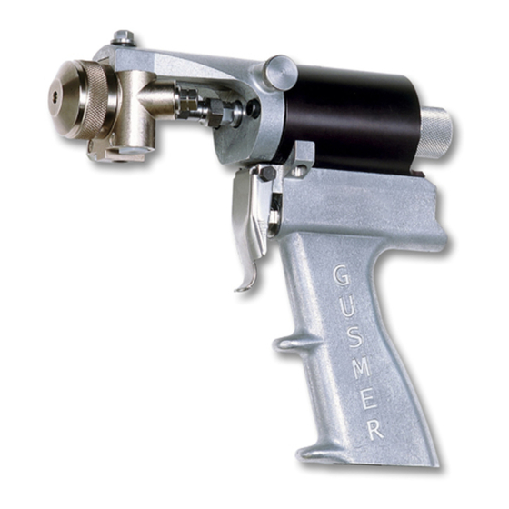
Overall View Overall View Gun Block Mounting Screw Safety Stop Air Cap Air Cap Air Adjustment Valve Gun Block Manual Valves Trigger Coupling . 1: GX-8P Overall View Block Centerline Components B-Screen Screw O-Ring Jam Nut Screen Screen Valving Rod Retainer Pattern Control Assembly... -
Page 6: Mixing Module
Overall View Mixing Module Valving Rod Graco offers a variety of spray tip configura- Assembly tions to meet most applications that spray Fan Spray fast-reaction chemical systems at low outputs. Pattern GX-8P spray tip components consist of a Pat- tern Control Disc (PCD) and a Mixing Module Mixing (Figure 3). -
Page 7: Operation Basics
OPEN position. Disengage the Grounding Safety Stop Check your local electrical code and propor- tioner manual for detailed grounding instruc- tions. Ground spray gun through connection to Graco-approved grounded fluid supply hose. . 5: Safety Stop - Disengaged 311338B... -
Page 8: Air Hose Connection
Operation Basics Air Hose Connection Coupling Block Chemical hoses are joined to gun block by a coupling block to ease installation and removal of gun. Connect Air Hoses Manual Valves Pull back sleeve of female fitting, insert male Two manual valves located on coupling block fitting and slide sleeve forward to secure con- control flow of each chemical component to nection. - Page 9 Operation Basics Close Manual Valves 3. Fit coupling block into gun block and insert coupling block mounting screw. Use 5/16 Use 5/16 in. nut driver to turn manual valve in. nut driver to tighten to gun block. fully counterclockwise. CAUTION To prevent accidental gun operation, always set safety stop to CLOSED, close both man- B-Check...
-
Page 10: Air Inlet Configuration
Operation Basics Air Inlet Configuration Mixing Module and PCD Installation There are two configurations for the air inlet. In the standard configuration, the air inlet is at 1. Loosen air cap by hand and remove. base of handle. In the alternate configuration, the air inlet is at rear of gun. -
Page 11: Valving Rod Adjustment
Operation Basics Valving Rod Adjustment 4. Use 3/8 in. wrench on hex-shaped valving rod shank and 1/2 in. wrench on jam nut to Valving rod should not require adjustment if it loosen and back it away from valving rod by was shipped from factory with mixing module 3 or 4 full turns. -
Page 12: Initial Set Up
Operation Basics Initial Set Up 6. Bleed air from chemical hoses: a. Hold coupling block with exit ports pointed into waste container. b. Use 5/16 in. nut driver to open each 1. Remove coupling block from gun. manual valve; this allows any trapped air to escape. -
Page 13: Daily Start-Up
Operation Basics Daily Start-up Daily Shutdown Ensure gun is attached to coupling block and air hose. Ensure proportioning unit is at Follow daily shutdown procedure when desired temperature and pressure. Properly gun is out of service for any length of time, ground equipment to avoid static sparking or for mid- or end-of-day service. -
Page 14: Pressure Relief Procedure
Pressure Relief Procedure Pressure Relief 4. Release gun trigger, CLOSE safety stop, and close manual valves. Procedure If fluid in hose and proportioner is still under pressure, follow Pressure Relief Procedure in Relieve pressure before cleaning or repairing proportioner manual gun. -
Page 15: Maintenance
Maintenance Maintenance Gun Service Kits Use either 1-Quart Gun Service Kit (296980) or 3-Gallon Gun Service Kit (296981) to per- form daily flushing of spray gun without disas- sembly. . 15: 3-Gallon Gun Service Kit For more information about 3-Gallon Gun Ser- vice Kit, see Manual 311341. -
Page 16: Flush Gun
Maintenance 4. Attach service block of gun service kit to 10. Clean screens, check valves and screen spray gun, and then tighten using 5/16 in. screw (see Service Screen Screw, page nut driver. 5. Pressurize service kit container up to 100 Inspect air cap, PCD, mixing module, and psi. -
Page 17: Repair
Repair Repair Remove Check Valve Shutdown proportioner and allow chemicals To avoid static sparking that may result in fire to cool before servicing gun. or explosion, ensure all equipment in flushing procedure is grounded. Do not flush on or near foamed or coated surfaces. Service Screen Screw Check valves are located in cavities of gun block under each coupling block gasket. -
Page 18: Remove Centerline Components
Repair Remove Centerline up on gun block, remove dried chemi- cals to make removal easier. Components 11. Remove and clean check valves (see Refer to page 5 for diagrams of centerline Remove Check Valve, page 17). components for all gun models. 12. -
Page 19: Replace End Cap And Air Piston Assembly
Repair Replace End Cap and Air 5. OPEN safety stop. Piston Assembly 6. To install mixing module, hold down gun trigger and slide module over end of valving #8 Socket Head End Cap rod. Make sure to align keypin with slot in End Cap/Safety Cap Screw O-Ring... - Page 20 Repair d. Use 3/8 in. wrench on hex-shaped valv- a. Remove piston/rod assembly: ing rod shank and 1/2 in. wrench on jam Use gun block mounting screw (screw nut. that holds gun block to bracket) to aid in removal of piston. e.
- Page 21 Repair Knob O-ring Spring End Cap Retaining ring must seat completely into Cup Seal groove to secure end cap in place when air cylinder is pressurized. Keep clear of cap when air pressure is applied or gun is trig- gered after reassembly. Set Screws 17.
-
Page 22: Replace Trigger Valve O-Rings
Repair Replace Trigger Valve c. Apply thin coat of Lubriplate grease to new rings and reinstall. O-Rings Follow steps 6-14 to replace rings on 1. Clean gun (see Clean Spray Gun Proce- valve liner. If rings do not need to be dure, page 15). -
Page 23: Clean Mixing Module
Repair 17. Use screw and locknut to reinstall trigger module from end of valving rod. CLOSE lever. safety stop. 9. Inspect valving rod for damage and replace Clean Mixing Module as required. Use cloth soaked in gun cleaner or steel wool to clean and remove 1. -
Page 24: Parts
Parts Parts GX-8 Gun Final Assembly (297898) 311338B... - Page 25 Parts GX-8 Gun Final Assembly (297898) Ref. Part Description Qty. Ref. Part Description Qty. 297702 HANDLE, assembly 295184 HOSE, air, 1/4 in. x 23 in. (F x F) 297684 RETAINER, PCD 295801 GASKET, block, gasket 297341 ROD, valving 295623 VALVE, check, A...
-
Page 26: Handle Assembly (297702)
Parts GX-8 Handle Assembly (297702) 311338B... - Page 27 Parts GX-8 Handle Assembly (297702) Ref. Part Description Qty. 296538 RING, retaining 297689 HANDLE, gun Ref. Part Description Qty. 297690 CYLINDER, air 295435 SEAL, u-cup 295686 LINER, valve 295709 SCREW, cap, socket head 297722 SPOOL, valve 295662 PLUG, pipe 295688 NUT, retainer, valve...
-
Page 28: Gx-8P Spray Gun Final Assembly (297860)
Parts GX-8P Spray Gun Final Assembly (297860) . 21: GX-8P Spray Gun Final Assembly 311338B... - Page 29 Parts GX-8P Spray Gun Final Assembly (297860) Ref. Ref. Part No. Description Qty. Part No. Description Qty. 295341 ROD, valving 295184 HOSE, air, 1/4 X 23 in. (F X F) 297861 CYLINDER, GX-8P, auto 295801 GASKET, block, gasket 297193 SCREEN, gun block, 295623 VALVE, check, A 100 mesh...
-
Page 30: Gx-8P Auto Cylinder Assembly
Parts GX-8P Auto Cylinder Assembly (297861) . 22: GX-8P Auto Cylinder Assembly 311338B... - Page 31 Parts GX-8P Auto Cylinder (297861) Ref. Ref. No. Part No. Description Qty. No. Part No. Description Qty. 42 297881 VALVE, control 26 295435 SEAL, u-cup 43 297882 MANIFOLD, air valve 27 295709 SCREW, cap, socket head 44 297883 GASKET 28 295732 SCREW, cap, sh, 45 296538 RING, retaining...
-
Page 32: Auto Gx-8P Optional Parts
Parts Auto GX-8P Optional Parts 2,3,4 2,3,4 Ref No. Part No. Description Qty. 297899 KIT, auto, GX-8 Gun 298752 WIRE, 10 ft, extension harness 298753 WIRE, 25 ft, extension harness 298754 WIRE, 50 ft, extension harness 298611 ENCODER, assembly 299083... -
Page 33: Coupling Block Assembly (295383)
Parts Coupling Block Assembly (295383) Ref. No. Part No. Description Qty. 295662 Pipe plug, flush seal, 1/8 in. 295888 B-swivel fitting 295889 A-swivel fitting 295693 Pipe plug, flush seal, 1/16 in. 296970 Manual valve assembly 296215 Coupling block 311338B... -
Page 34: Coupling Block (297902)
Parts Coupling Block (297902) Ref. Part No. Description Qty. 0377 PLUG, pipe 2105C VALVE, assembly, manual IP31140-1 Block, coupling 311338B... -
Page 35: Set-Up Chart For Gx-8P Modules
Parts Set-up Chart for GX-8P Modules Pres- Pattern Resin ✖Dia. sure Output Module Part Port Iso Port (psi) (lbs/min) (inches) Size Orifices Size Orifices Round Spray Pattern 2500 295377 .013 .013 295339 (020) 2500 295377 .013 .013 295428 (024) Fan Spray Pattern 2500 295338 .013... -
Page 36: Gx-8P Model Specifications
Parts GX-8P Model Specifications Module/Tip Data for Chemical Sprayed at 2500 PSI ❄Output ✖Module Kit ❄Pattern Cleanout Drill (lbs/min) Fan Spray Pattern 295338 297914 297192 (201) 6 in. wide (.098 diameter) (.013 diameter) 297841 (202) 7 in. wide Round Spray Pattern 295377 297914 295339 (020) -
Page 37: Technical Data
Technical Data Technical Data Category Data Air Supply 100-125 psi (7-9 bars) Maximum Operating Pressure 3500 psi (24 MPa, 240 bar) Maximum Output ❄ 0.4 gallons/min. (1.52 liters/min.) Minimum Output ❄ 0.1 gallons/min. (0.38 liters/min.) Height 7 in. (17.8 cm) Length 7.5 in. -
Page 38: Notes
Notes Notes 311338B... -
Page 39: Graco Standard Warranty
Graco, Graco will, for a period of twelve months from the date of sale, repair or replace any part of the equipment determined by Graco to be defective. This warranty applies only when the equipment is installed, operated and maintained in accordance with Graco’s written... -
Page 40: Graco Information
Graco Information TO PLACE AN ORDER, contact your Graco distributor or call to identify the nearest distributor. Phone: 612-623-6921 or Toll Free: 1-800-328-0211, Fax: 612-378-3505 All written and visual data contained in this document reflects the latest product information available at the time of publication.
Need help?
Do you have a question about the GX-8 and is the answer not in the manual?
Questions and answers