Advertisement
Quick Links
Advertisement

Related Manuals for luxvision RU-1400


Summary of Contents for luxvision RU-1400
- Page 2 Notification Dear Users, Thank you for your purchase of RU 1400 Refraction Unit. Please take time to read our user’s manual carefully before use. This guarantees you to make full use of this unit and prolongs the operation life of this unit.
-
Page 3: Table Of Contents
Content Package List ....................4 Name of Parts ....................7 Assembly Process ..................9 Default Circuit Settings and Adjustment ............15 Operation ....................16 Possible failure and Repair ................18 Wiring Diagram ....................19 Specifications ....................22... -
Page 4: Package List
1. Package List Name Qty. Figure MainPart (including Base, Liftpart and Operating Board). Rocker ShortRod LongRod Lamp... - Page 5 Name Qty. Figure Back Cannula Hex Socket Cap Screw ISO 4762-M8X120 Projector Flat and Countersunk Flat Head Screw Power Cable Communication Cable Fuse 5A...
- Page 6 Name Qty. Figure Hex Spanners Wrench Manual Acceptance Certificate...
-
Page 7: Name Of Parts
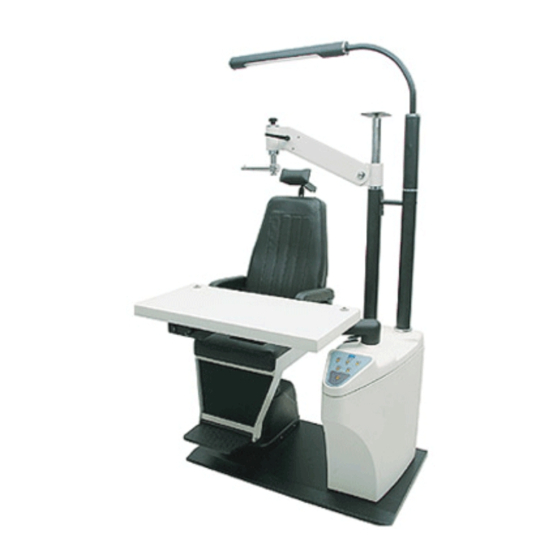
2. Name of Parts Refer to figure 16 and Figure 1 to understand the instrument’s components. Fig.1 Components diagram (1) - Page 8 Fig.2 Components diagram (2) 1. Projector Flat 11. Chair Cover 20. Rocker locker 2. Rocker Installing Rod 12. Baffle 21. LongRod 3. Rocker 13. Footboard 22. Connector Pipe 4. Back 14. Base 23. Lamp 5. Armrest 15. Mainframe 24. Screws 6.
-
Page 9: Assembly Process
3. Assembly Process First at all, you should place the MainPart on a flat. Unscrew the two screws on the back of the MainPart, so you can open it’s back (fig.3) Fig.3 Unfix the back Unscrew the screw and washer on the end of the ShortRod (fig.4) Fig.4 Unscrew screw and washer Fit the ShortRod on the MainPart according to the place showed in figure 5. - Page 10 Fig. 5 Assembly ShortRod Before mounting the LongRod on the MainPart with the same way as step 3 ~ 4, you should unscrew the screw and washer at the end of the LongRod (see fig.6), and the four screws on the other end of it (fig.7). See Figure 6 ~ 8. Fig 6 Unscrew the screw and Fig.7 Unscrew the four screws washer on LongRod...
- Page 11 Fig. 8 Assembly LongRod Place the Cannula between the Rods, and adjust the Rods’ position to keep the three holes in line. Insert the Hex Socket Cap Screw ISO 4762 - M8x120 into the ShortRod. Cannula and the LongRod. Before fixing the screw, you need to adjust the ShortRod and the LongRod, keep them vertical to the ground.
- Page 12 In order to keep the lamp horizontal, one person should buttress the lamp in this step. Adjust the lamp to the right position, and fix the four screws unscrewed from the LongRod to the corresponding position and make them tightened, (fig.7). See the figure 11.
- Page 13 Fig.13 Fix the Back Hang the Rocker onto the ShortRod, make sure that the Rocker can run softly and comfortably. See figure 14. Fig.14 Assembly the Rocker To install the Projector Flat with the Countersunk Flat Head Screw. Keep the length of the power plug wire 260mm,see figure 15.
- Page 14 Projector Flat and Countersunk Flat Head Screw Fig. 15 Assembly the Projector Flat Connect the Projector wire and lighting wire respectively according to the connection diagram (see figure 16). Lighting wire AC Input Projector wire Fig.13 Connection diagram Power on to test the wire connection. If connection is correct, fix the back of MainPart (fig.17);...
-
Page 15: Default Circuit Settings And Adjustment
Other Accessories Assembly To install the Projector onto the Projector Flat with the screws, and plug in. Hang up the Eyesight Detector onto the HorizontalRod of the Rocker, tighten its locking knob. Adjust the position of the detector via the handle on the Rocker, and then adjust it’s horizontality via the bubble cell on it. -
Page 16: Operation
in Fig 20), please take off the circuit ring (see No.2 in Fig 19) About the two DC output on the platform. When the platform rotates outside 20 degrees, the power shut off. When the platform rotates back inside 20 degrees the power continues. - Page 17 and then rotate the Board 90-degree. When you have to do some eyesight examinations, you can move the Eyesight Detector to the front of the patient, pull down the Rocker (No. 3 in fig. 1) to a suitable position, and lock the Rocker with it’s locker (No. 20 in fig. 1). If there is needed to adjust the height of the chair, do it as step 3;...
-
Page 18: Possible Failure And Repair
6. Possible Failure and Repair Here are some frequent failures or something happened possibly when you operate this combined table. You can examine the facility or repair it according to the list. Failures Possible reasons and repair suggestion Checking the fuse. The indicator light has no light when power on Checking the status of the socket. -
Page 19: Wiring Diagram
7. Wiring Diagram The electric principle map... - Page 20 The electric system map...
- Page 21 The line sketch map...
-
Page 22: Specifications
8. Specifications Mechanical Parameters Angle of rotation for swing arm ±30 Table size(mm) 840 x 405 Angle of rotation for table 90° Table rnovement 0 ~ 330mm Angle of rotation for chair Lifting height for chair 0-180mm Loading for chair 150Kg Lifting height for pillow 0 ~ 70 mm... - Page 23 Main Wire 10A 250V Working Temperature -30°C ~ +50°C Relative Humidity less than 90% Force of Pressing key 1 ~ 5N Cooling mode Nature cooling Installation Dimension Figure size: 1400mm x 1000mm x 1990mm Weight: 98Kg...
- Page 24 LUXVISION, Inc. shall not be liable for any errors or for incidental or consequential damages in connection with the furnishing, performance, or use of this manual or the examples...
Need help?
Do you have a question about the RU-1400 and is the answer not in the manual?
Questions and answers