Table of Contents
Advertisement
Quick Links
Advertisement
Table of Contents

Related Manuals for luxvision SL 1400


Summary of Contents for luxvision SL 1400
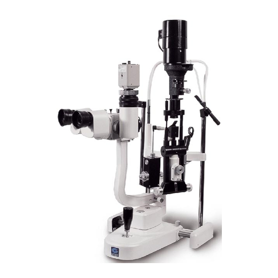
- Page 1 USER’S MANUAL SLIT LAMP SL 1400...
- Page 2 Notification Dear Users, Thank you for your purchase of SL 1400 Slit Lamp. Please take time to read our user’s manual carefully before use. This guarantees you to make full use of this unit and prolongs the operation life of this unit.
-
Page 3: Table Of Contents
Content Name of Parts....................4 Assembly....................... 8 Operation....................19 Maintenance....................28 Common Trouble Shooting................. 35 Optional Photographic Attachment............. 37 Optional Observation Tube................65 Optional TV Accessories................67 Optional Barrier Filter.................. 68 10. Applanation Tonometer................69 11. 12.5x measuring eyepieces................. 70 12. -
Page 4: Name Of Parts
1. Name of Parts... - Page 5 1. Joystick Incline joystick slightly to move the instrument in the horizontal plane and rotate it to adjust the elevation of the microscope. 2. Base Locking Screw The base will be locked when this screw is tightened. 3. Rail Cover Protects the rail surface 4.
- Page 6 14. Microscope and Illumination arm Coupling Bolt Tightening this bolt permits the illumination arm and the microscope arm to be rotated simultaneously. Loosening the bolt allows the illumination arm and microscope arm to rotate separately. 15. Hruby Lens Guide Plate The plate is also used for the applanation tonometer.
- Page 7 29. Aperture and Slit Height Control Knob Rotate this knob to adjust the spot and the slit height. Turn the knob horizontally to rotate the slit. 30. Fixation Target An illuminated fixed spot for patient to look at. 31. Reflecting Mirror Both long and short reflecting mirrors are provided.
-
Page 8: Assembly
2. Assembly Components... - Page 10 Name Quantity Illumination Part Microscope (with 10x eyepieces) Base Part Head-Rest Part Breath Shield Worktable with Power Box Rail Cover Input Power Cable Hruby Lens Hruby Lens Guide Plate Spare Main Illumination Bulb Chin-Rest Paper Focusing Test Rod Protection Cap Dust-Proof cover Fixation Target Spare Long Reflecting Mirror...
- Page 11 1. Selecting voltage and fuse Fuse holder Voltage selector Selector voltage and fuse • Check the setting on the voltage selector located on the bottom of the power box. If it doesn’t match with the input voltage, slide it to the proper position with screwdriver (V).
- Page 12 • Place the worktable so that the power panel faces the user, then refasten the bolt securely with the wrench. Assembling the Head-rest Part (D) Head rest fixation plate Chin rest connection board • Remove the four screws attached to the chinrest connection board with the screw driver (U).
- Page 13 • Put two cables in the gap between the headrest fixation plate and the chin- rest connection board. • While ensuring the cables are not compressed, retighten the previously removed screws. 4. Assembling the base part (C) and the rail covers (G) Wheel Rail •...
- Page 14 • Rotate the brass shaft sleeve to make the angle of the red mark and the illumination arm between 30º and 90º. • Loosen the screw on the illumination arm with the screwdriver (V). Align the assembly hole of the illumination arm to the brass shaft sleeve and lower carefully, while simultaneously aligning the two red marks.
- Page 15 7. Assembling the breath shield (E) Important Matters Avoid touching any lens surface while assembling the breath shield (E). • Remove the breath shield fixation screw from the microscope arm. • Pass the removed screw through the hole of the breath shield then re-screw it into the arm.
- Page 16 Connecting Plug • Remove the sticky shipping tape from the cap. The tape ensures that the cap is remains fastened to the lamp base during transportation. Sticky tape • Insert the plug on the top of the headrest part (D) into the socket of the lamp cap (26) on the illumination part (A).
- Page 17 10. Assemble the Hruby Lens (I) • Insert the Hruby lens ( I ) into the Hruby lens holder (26) on the headrest part. Be careful not to touch the lens surface. • Place the Hruby lens guide plate (J) into the main shaft hole of the base part with the small end pointed at the headrest part.
- Page 18 12. Storing spare parts Spare parts may be stored in the accessory drawer. Inspection procedure after assembly 1. Power plug • This instrument supplied with a 3-wire grounded line cord. Do not remove or disconnect the ground. Please select proper power sockets and plugs •...
-
Page 19: Operation
2. The power box and the illumination part • When the main power switch (8) of the power box is placed at “1” it turns on, and when located at “0” it turns off. The main power switch should be set to the “0”... - Page 20 The focusing test rod is used to confirm that the microscope is adjusted correctly. Insert it into the main shaft hole with the flat surface facing the objective lens in the direction of the user. Important Matters After adjustment, remember to remove the rod and insert the protective cap. 2.
- Page 21 4. Pupillary distance adjustment Separate the prism boxes of the microscope with both hands to adjust the pupillary distance until both eyes can stereoscopically see the same image on the focusing test rod. Patient position and fixation target 1. Positioning the patient’s head Have the patient place his chin on the chin-rest (17) and the forehead against the forehead belt (24).
- Page 22 Curved level Fixing screw Fixaation target bar Adjusting knob The fixation target with the spot light is intended for the patient whose diopter exceeds – 15D. When changing, just loosen the fixation screw, replace the fixation target with the spot light source and tighten the fixation screw. Base operation 1.
- Page 23 White watching through the eyepieces, tilt the joystick to align the microscope at the object for a sharp image. 4. Locking the base When finishing the adjustment, fasten the base locking screw (2) to lock the base (4) and prevent it from sliding. Illumination parts operation 1.
- Page 24 respectively. With a slit image, the slit height can be changed continuously from 1 to 9mm, which is indicated by the display window (27). Scale 3. Rotating the slit image Swing the aperture and slit height control knob (29) horizontally to revolve the slit image at any angle from vertical to horizontal.
- Page 25 This feature is used primarily for examination by indirect retro-illumination. Tighten the centering knob and the slit light will return to the center of the microscope’s field of vision. 5. Oblique Illumination Oblique illumination is used for sectional or fundus examination by use of a contact lens.
- Page 26 Long mirrow Short mirrow 7. Filter selection Move the filter selection lever (28) in the horizontal plane to add or remove the four filters in the illumination path. Usually the heat absorption filter is used so that the patient may feel more comfortable during a long examination. No filter Blue filter Heat-absorpting filter...
- Page 27 To use Hruby lens proceed as follows: 1. Dilate he patient’s pupil for about 20 minutes. 2. Insert the Hruby lens guide plate (15) into the main shaft hole of the illumination arm and the microscope arm. 3. Pull out the Hruby lens holders from one side of the headrest. Move the Hruby lens holder toward user so that it can slide freely to the left and right below the chin-rest.
-
Page 28: Maintenance
Lever Groove 4. Maintenance Important Matters Dispose of replacement parts in accordance with local regulations. Replacing the illumination bulb • Turn the main power switch (8) off. • Unplug the connector on the lamp housing. • Rotate the lamp cap (26) counter clockwise and remove it from the illumination part (A). - Page 29 • Remove the old bulb and replace it with a new one. The groove in the bulb fixation disc should be aligned with the flange of the lamp base. Improper alignment may cause uneven illumination. Bulb Fixation disc Flange Important Matters The bulb is hot •...
- Page 30 • Incline the illumination arm more than 10º. • Remove the long mirror by holding the extended surface. • Insert new long or short reflecting mirror. Replacing the fuse • Turn off the main power switch (8) and unplug the power cord from the power socket.
- Page 31 • Remove and replace the fuse, replace the fuse cover. • The fuse specifications are as follows: 110V 1A, 250V 220V 0,5A, 250V Important Matters Please select the fuse of the same type, specification and rated value. Replacing the chin-rest paper When the paper is exhausted, remove the pins by pulling them upward out of the chin-rest.
- Page 32 Screw Left knob Right knob When the desired tightness has been achieved, tighten the locking screw on the right knob. Adjusting the inclination of the illumination part If the inclination mechanism of the illumination part is too loose, tighten the screws on both sides of the pivot point with the screw driver (U).
- Page 33 Important Matters Never touch the lenses of mirrors with your fingers or any hard materials. 2. Cleaning the slide plate, rail and shaft Wipe the dirty segment with clean soft cloth. 3. Cleaning the plastic parts Clean the plastic parts such as the chin-rest bracket and forehead belt with soft cloth moistened with a mild detergent or water.
- Page 34 Consumable Parts Please specify names and quantities when ordering following consumable parts. Part name Outlook Illumination Bulb Short Mirror SL 1400 Slit Lamp Long Mirror Chin-rest paper Fuse 1 A (110 V) Fuse 0,5 A (220V)
-
Page 35: Common Trouble Shooting
5. Common Trouble Shooting In case there is any trouble, please refer to the following table. If the equipment still doesn’t work, please contact the Repair Department or an authorized distributor. Trouble Possible Cause Remedy No illumination The cable isn’t connected Connect the power cable correctly with the power correctly. - Page 36 Trouble Possible Cause Remedy The fuse doesn’t comply Replace it with a suitable with the specification. fuse. Slit closes The slit width control knob Adjust the tightness of automatically is too loose. the control. Fixation target The output plug is loose. Insert the output plug position firmly.
-
Page 37: Optional Photographic Attachment
6. Optional Photographic Attachment Name of parts... - Page 38 37. Shutter remote button Set the button at “S” or “T” position to open the shutter 38. F10-11 Motor drive Advance film automatically 39. DF-300 Body The image in the right ocular is photographed 40. Flash lamp mount 41. Photographic attachment detach/attach lever Attaches and detaches the photographic attachment to the main body of the slit lamp 42.
- Page 39 53. Shutter speed selector When using the flash, the shutter speed is set at 1/30 second. 54. Frame counter 55. Manual shutter 56. Shutter speed window 57. Lens detach/attach index 58. Accessory outlet 59. Power switch of camera 60. Rewind knob 61.
- Page 40 66. Film Cartridge Chamber 67. Winder crank When the motor drive is shut off, you can rewind the film by turning this crank. 68. Sprocket 69. Take-up spool 70. Back cover 71. Battery chamber button of the motor drive To open the battery chamber, press buttons at both sides to remove the cover.
- Page 41 the switch at the “S” or “C” position, then the lamp illuminates. “S” means single wind, “C” means continuous wind. 72. Fixing Screw 73. Power Indicator 74. Alarm lamp The lamp illuminates while the film advances, after the shutter is closed. When all frames have been exposed, the lamp will still light.
- Page 42 Name Quantity Photographic power supply DF-300 Body F10-11 Motor–Drive Relay lens unit Beam splitter Special lens for photography Xenon lamp Power cable Xenon relay cord Background illumination unit Synchronizing line Xenon lamp mount Remote shutter line Spare fuse *Assembled to the slit lamp Assembly These instructions describe the installation of the photographic unit for LSL 1400 for future reference.
- Page 43 Fuse holders Voltage selector Tools Required M2 Watch screwdriver M3 Phillips Screwdriver 1. Selecting the voltage and fuse • Check the voltage selector on the power supply.If it doesn’t match the mains voltage, slide it to the proper position with screw driver (V). •...
- Page 44 Unscrew the four knurled nuts from the lamp housing, remove the lamp housing and bulb. Hole • Insert pins in the long screw hole, and unscrew the four screw rods. Relay lens Hole • Mount the relay lens Screw...
- Page 45 • With the notch on the lamp house facing the user, tighten the four M3 X 10 screws. • Insert and tighten the four previously removed screw rods into the screw holes in relay lens unit. • Install the lamp housing and install the knurled nut. •...
- Page 46 4. Assembling the Xenon relay cord (I) Remove the four screws from the support rod portion of the chin-rest. With the plastic clips route the cord and replace the screws. The end connecting the Xenon relay cord must be long enough (about 40 cm) so that the other end connects to the power supply relay cord.
- Page 47 • Insert the Xenon lamp into the square cord in the side of the relay lens unit (D) in the up direction so that the opening in the flash housing will be facing the background illumination bundle. Hole Outlet • Mount the lamp assembly as shown.
- Page 48 Fixing screw Fixing screw Joystick Groove • Align the pin on the microscope body with the groove on the beam splitter. • Tighten the fixing screw to secure the beam splitter to the microscope body. • Using the previous orders of steps, reassemble the binocular head and tighten the fixing screw.
- Page 49 8. Attaching the camera • While pressing the lens-release button, turn the camera body counter clockwise as far as it will go, then lift out the lens blank. Red index • Align the red index marks on the special lens (F) with the red mounting-release index (57) on the camera’s body, then turn the lens clockwise until it locks in position with a click.
- Page 50 • Align the groove on the port of the lens with the pin of the beam splitter and insert it. Tighten it with the screw ring. • Align the clamp bolt (72) with the screw hole of the tripod at the bottom of the camera, and fasten it.
- Page 51 11. Assembling the remote shutter line (M) • Screw one end of the remote shutter line into the remote cord socket (63). • Place the other end of the remote shutter line near the operation knob. Inspection Procedure 1. Checking power plug •...
- Page 52 Operational procedure 6.5.1 Loading film 1. Open the camera and turn the motor-drive switch on. To prevent the film from advancing, do not touch the shutter release button. 2. Lift the rewind knob to open the camera. Place film spool in chamber while keeping the rewind knob lifted. 4.
- Page 53 6. If manual film advance is desired, be sure to turn the motor-drive off. 7. Ensure that film is not slack and spool is in place, if it isn’t, turn rewind crank clockwise until it stops, correctly tensioning the film, and repeat steps 5 and 6. 8.
- Page 54 Important Matters In view of the low magnification at 6X, photography is not recommended due to insufficient magnification and insufficient illuminated range. Microscope Photographic Magnification magnification Impossible 1.0 X 1.6X 2.5X 4.0X 6.5.3 Exposure Setting Determination suitable exposure values is based on the following: •...
- Page 55 Photographic Magnification 1.0X 1.6X 2.5X 4.0X (microscope magnification) (10X) (16X) (25X) (40X) Cornea Crystalline lens (Slit width 0.1 mm) Anterior portion Background Illumination H Diffusion lens illumination Iris Iris Full Slit Aperture Illumination (9mm) Diffusion lens illumination Conjunctiva Background illumination H Diffusion lens illumination Important Matters The gray areas in the table indicate that the photographic combination of conditions...
- Page 56 • When the diffusion lens is being used set the slit size to full aperture (9mm) and set the background illumination setting to the occluded position. 6.5.5 Precautions • Set the joystick of the full frame attachment at the “IN” position. •...
- Page 57 6.5.6 Removing the film Important Matters If the film sprocket holes are damaged, the film may not advance. Multiple exposures may be made on the same frame. • The alarm lamp lights when the film is exhausted. Turn motor–drive switch off, and check film frame number.
- Page 58 3. Background illumination High intensity (Move to the right end) Low intensity (Click at the center) Occluded (Move to the left end) • When using slit photography, the background illumination unit provides 3 settings: Low, High intensity and, Occluded. • If the illumination is used while the background illumination is in its normal position, ensure the background illumination unit doesn’t come in contact with either the lens or the finger supporting the lens.
- Page 59 • In the inclined illumination setting, the background illumination will be directed onto the reflection mirror. Therefore the object will not be illuminated by the device. • When using background illumination, there is no influence on the observed image. Only the slit illumination will influence the observed image. Background illumination 6.5.7 Diffusion Lens...
- Page 60 • When using diffusion lens, set the slit size to the full aperture setting, otherwise the illumination intensity will be reduced. At the same time, occlude the background illumination. Maintenance 6.6.1 Replacing the Xenon lamp If the Xenon lamp becomes discolored or sufficient light for photography is not provided, replace the Xenon lamp as follows: •...
- Page 61 • Do not touch the glass tube on Xenon lamp. Any foreign matter on the lamp such as fingerprints will result in the cloudiness that will shorten its service life. 6.6.2 Replacing the fuse • Turn off the power switch (50), remove the power cable (H) from the input outlet.
- Page 62 Part name Outlook Xenon lamp SL 1400 Slit Lamp Fuse T3.15A (110 V) Fuse T1.6A (220 V) • When using diffusion lens, set the slit size to the full aperture setting, otherwise the illumination intensity will be reduced. At the same time, occlude the background illumination.
- Page 63 Trouble Possible Cause Remedy Shutter does Power switch on the camera Turn power switch “ON” not open is “OFF” Motor–Drive switch is ”OFF” Turn motor–drive switch “ON” Batteries in camera are dead Replace batteries Batteries in motor–drive are Replace batteries dead Shutter release button set Set shutter release button “S”...
- Page 64 Trouble Possible Cause Remedy Slit size is not set at full Set the filter lever to full aperture, (except when using aperture (9mm) direct diffusion illumination) Charging cycle is not Wait until charge lamp completed illuminates Selection lever for Select the correct position background illumination is out of position Flash intensity set wrong...
-
Page 65: Optional Observation Tube
6.6.6 Specifications Optical axis for photography Right ocular pathway Photographic magnifications 0.6X, 1.0X, 2.5X, 4.0X Camera SEAGULL DF-300 35 mm Motor-Drive SEAGUL F10-11 Background illumination Light guide illumination 3 – setting Light for photograph Pulse Xenon Lamp Input Voltage 110/220 V + 10% Frequency 50/60Hz + 1 Hz Flash power... - Page 66 Locking ring Flitting ring Joystick Specifications Eyepiece: 12.5X Magnification: 6X, 10X, 16X, 25X, and 40X Beam splitting proportion: 50:50 Image rotation angle: 360º Assembly • Attach the beam splitter (Refer to page 24) • Remove the protective cover from the observation tube. •...
-
Page 67: Optional Tv Accessories
TV camera Locking ring Joystick Relay lens 8. Optional TV Accessories Features • Provides demonstration ability to a large audiences • Allows images to be placed on videotapes Specifications Magnification Observation Mag. TV relay Mag. TV Field of View 0.1X 21.75 X 29.0 1.0X 13.9 X 18.56... -
Page 68: Optional Barrier Filter
Setup Adjust the diopter of the eyepieces. Assembly • Attach beam splitter (Refer to page 25) • Remove the protective covers in both sides of the relay lens. • Align the teeth on the beam splitter to the grooves on the relay lens, insert the relay lens securely, rotate the locking ring to secure the beam splitter. -
Page 69: Applanation Tonometer
• Provides ability to observe and photograph the anterior section of the eye using fluorescence Lever Fixing screw Specification Separation wavelength: 520nm Assembly • Use set screws to mount the barrier filter. How to use • Rotate the eyepiece adjustment ring and adjust the diopter compensation. •... -
Page 70: 5X Measuring Eyepieces
• Loosen the locking ring on the relay lens, and remove the TV mount. • Attach the TV mount to the TV camera. • Insert the TV camera and mount into the relay lens, with the camera base facing you lock it with a locking ring. 11. -
Page 71: Resopnsibility
11.2 Specifications • Scale specification Length scale 16mm (0.5mm graduations) Angle scale 360º (5º graduations) • Measuring parameters Length scale To be used at 10x only Diopter compensation -5D to +3D Angle scale No limitation 12. Responsibility We will supply the circuit diagram, electrical component list, drawing annotation and calibration instructions according to each customer’s needs. -
Page 72: Specifications
14. Specifications Microscope Type Galileo, magnification changer with stereoscopic head Model of magnifying 5 steps via ring rotation Eyepiece 12.5X Total magnification 6X, 10X, 16X, 25X, 40X Field of view (33mm)(22.5mm)(14mm)(0.8mm) (5.5mm) Range of PD adjustment 55mm to 75 mm Diopter adjustment -5/+3D Illumination... - Page 73 Movement base Fore and back movement 90mm Left and right movement 100mm Fine movement 15mm Vertical movement 30mm Chin – rest parts Vertical movement 80mm Fixation target Red Led Hruby Len Hruby Lens -58.7D (optionally available in some regions ) Power source Input voltage 100/220V + 10%...
- Page 74 LUXVISION, Inc. shall not be liable for any errors or for incidental or consequential damages in connection with the furnishing, performance, or use of this manual or the examples...
Need help?
Do you have a question about the SL 1400 and is the answer not in the manual?
Questions and answers