Advertisement
Quick Links
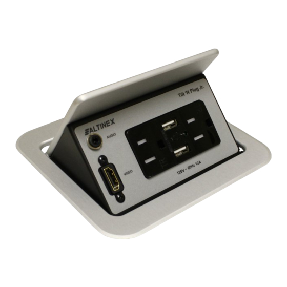
TNP358 Tilt 'N Plug
elcome!
We greatly appreciate your purchase of your TNP358 Series Tilt
'N Plug. You will find the TNP358 to be reliable and simple to use.
We are committed to providing the best Signal Management
Solutions® to our customers.
We are committed to providing our customers with
Signal Management Solutions
audiovisual installations at competitive pricing and we welcome
you to join the ranks of our many satisfied customers throughout
the world.
1. Precautions and Safety Warnings
Please read this manual carefully before using your TNP358 Tilt
'N Plug interconnect box. Keep this manual handy for future
reference. These safety instructions are to ensure the long life of
your Tilt 'N Plug and to prevent fire and shock hazards.
1.1 General
Unauthorized personnel shall not open the unit or cable
assembly as there are high-voltage components inside. Only
qualified Altinex service personnel or their authorized
representatives must perform all service.
2. Installation Procedures
Note:
Download and read the entire online manual to become familiar with the TNP358 and for detailed installation instructions.
Step 1. Cut an opening into the table's surface. Refer to the Altinex website at
http://www.altinex.com/
performed by experienced professionals in order to insure accuracy and to be
aesthetically pleasing.
NOTE: The table should be 2.25 in (57 mm) or less in thickness. Always confirm
dimensions before cutting to insure that specifications have not changed.
Step 2. Insert the TNP358 into the table cutout.
Step 3. Place the support brackets under the table between the support mount grooves on the
side of the unit. Attach the brackets to the groove at the desired height and secure them
to the bottom of the table using the knurled table securing screws. Tighten wing nuts to
secure the screw in place.
Step 4. To lower the unit, push on the top cover until it locks into place.
Step 5. Secure the power cable to the underside of the table using the cable clamps and screws included. Feed the power cord from
the bottom of the TNP through the cable clamps, but leave enough slack in the service loop for easy opening and closing. Too
much slack can cause excess drooping of the service loop. Secure the power cord separate from other cables.
Step 6. To raise the unit into position, push down on the front of the top cover to release the latching mechanism, allowing the TNP to
raise it into position.
NOTE: It may be necessary to adjust the power cable service loop for optimal performance.
3. Limited Warranty/Return Policies
Please see the Altinex website at
400-0614-001
INTERCONNECT BOX
®
®
to the most demanding
for table cutout requirements. This operation should be
www.altinex.com
for details on warranty and return policies.
1.2 Installation Precautions
For best results, place the Tilt 'N Plug in a dry area away
from dust and moisture. To prevent fire or shock, do not
expose this unit to water or moisture. Do not place the unit in
direct sunlight, near heaters or heat-radiating appliances, or
near any liquid.
Handle carefully; dropping or jarring can damage the bezel.
Never place fingers inside the opening on either side of the
unit. This action could cause injury due to sharp edges
inside.
Do not place heavy objects on top of the Tilt 'N Plug. Do not
use excessive force to push down on the top of the unit.
Disconnect the power cord to turn power off.
Install all cables according to the instructions found in this
user guide. Do not force or pull any cable that is attached to
the Tilt 'N Plug.
1.3 Cleaning
Surfaces should be cleaned with a damp cloth. Due to the
chrome finish, do not use any abrasive solutions.
1
User's Guide
Advertisement

Subscribe to Our Youtube Channel
Related Manuals for Altinex SIGNAL MANAGEMENT SOLUTIONS Tilt ‘N Plug TNP358 Series


Summary of Contents for Altinex SIGNAL MANAGEMENT SOLUTIONS Tilt ‘N Plug TNP358 Series
- Page 1 Note: Download and read the entire online manual to become familiar with the TNP358 and for detailed installation instructions. Step 1. Cut an opening into the table’s surface. Refer to the Altinex website at http://www.altinex.com/ for table cutout requirements. This operation should be performed by experienced professionals in order to insure accuracy and to be aesthetically pleasing.
- Page 2 User’s Guide TNP358 4. Technical Specification Specifications are subject to change. Please visit http://www.altinex.com for up-to-date specification Features/Description TNP358* Mechanical TNP358** General Max. Table Thickness 2.25 in (57 mm) Outputs Height, opened 5.88 in (149 mm) USB Charging USB 2.0 Type A F (2) Height, closed 3.80 in (97 mm)
- Page 3 The next time you need to spruce up your customer's boardroom or university classroom, look no further than Altinex. So give us a call. We design, build, and support our products from the beautiful city of Brea in Southern California.
- Page 4 User’s Guide TNP358 6. Application Diagrams Diagram 1: Application diagram for TNP358 400-0614-001...
- Page 5 User’s Guide TNP358 Diagram 2: Front View 400-0614-001...
- Page 6 User’s Guide TNP358 Diagram 3: Mounting 400-0614-001...
- Page 7 User’s Guide TNP358 Diagram 4: Side Dimensions 400-0614-001...
- Page 8 User’s Guide TNP358 Diagram 5: Side Dimensions 400-0614-001...
- Page 9 Make sure that power cord is not damaged or pinched. Damaged power cord If there has been damage, do not use the Tilt 'N Plug. Please call the Altinex Customer Service Department at (714) 990-2300 to have the unit returned for repair.
Need help?
Do you have a question about the SIGNAL MANAGEMENT SOLUTIONS Tilt ‘N Plug TNP358 Series and is the answer not in the manual?
Questions and answers