Table of Contents
Advertisement
Quick Links
SPA V1.0 ASSEMBLY
Before starting this kit, prepare the following tools: Soldering iron (1520W will do),
multimeter, protective eyewear, flush cutters, n2. hex screwdriver or allen key, phillips
screwdriver and some coffee. Also briefly go through this guide and make sure that you
understand all the steps, if you are having any troubles don't hesitate to seek help at the
forum.
We suggest that you work in a clean and a well lit environment to avoid accidents or losing
any of the small components.
IMPORTANT!
If you have never soldered before, check out this great
DOWNLOADS
● schematics and board diagram –
● And the Bill of Materials (BOM) –
● user manual –
And please check that your boards are the same version as this guide and that your kit
contains the following items:
P DF
G oogledocs
P DF
t utorial first
.
Advertisement
Table of Contents

Related Manuals for Bastl Instruments SPA V1.0


Summary of Contents for Bastl Instruments SPA V1.0
- Page 1 SPA V1.0 ASSEMBLY Before starting this kit, prepare the following tools: Soldering iron (1520W will do), multimeter, protective eyewear, flush cutters, n2. hex screwdriver or allen key, phillips screwdriver and some coffee. Also briefly go through this guide and make sure that you understand all the steps, if you are having any troubles don’t hesitate to seek help at the forum. We suggest that you work in a clean and a well lit environment to avoid accidents or losing any of the small components. IMPORTANT! If you have never soldered before, check out this great t utorial first . DOWNLOADS P DF ● schematics and board diagram – ● And the Bill of Materials (BOM) – G oogledocs ● user manual – P DF And please check that your boards are the same version as this guide and that your kit contains the following items: ...
-
Page 2: Bom - Bill Of Materials
BOM – BILL OF MATERIALS 1 x 10kΩ 0,4W 1% resistor 1 x 2x5 pin male pinheader 4 x pot knob 6 x 100nF capacitor 1 x 6 pin male pinheader 1 x programmed Atmega328 2 x 10μF capacitor 1 x 10 pin female pinheader 1 x 11mm spacer 1 x 1N4007 DIODED7.5 4 x 100RΩ 0,4W 1% resistor 1 x 10mm spacer 1 x 7805 voltage regulator 2 x 1kΩ 0,4W 1% resistor 6 x jack washer 1 x 16MHz resonator 2 x 100kΩ 0,4W 1% resistor 6 x jack nut 1 x 100mA PTC fuse 1 x switch 2 x 6mm screw 1 x MCP6002 IC in foam 6 x jack connector 2 x 8mm panel screw 1 x MCP6004 IC in foam 1 x 10 pin male pinheader 1 x imbus key 1 x 8 pin DIL socket 4 x 100k lin potentiometer 1 x 10 to 16 pin power cable 1 x 14 pin DIL socket 1 x top PCB 1 x 6 pin cable 1 x 28 pin DIL socket 1 x bottom pcb 1 x laser engraved panel We even included some of the best quality solder we found to help you solder everything faster. ... - Page 3 Next place and solder the sockets. Make sure that the notch is in the s ame direction as printed on the circuit board. ...
- Page 4 Then add the capacitors, there are six 100nF capacitors (marked 1 04 , follow the link for more details on capacitor codes) . They might be in ceramic or polyester film package, don’t worry they are not polarized. Now move on to the TPC fuse. It looks quite similar to a ceramic capacitor and are placed in the blank rectangular markings on the board near the voltage regulator. Also solder the 7805 voltage regulator. Bend its leg as close to the body as possible, at a right angle to make sure that it lies flat on the circuit board. Your board should look like this: ...
- Page 5 Now, it’s time for more capacitors. Take the two 47μF capacitors and place them on the front side of the board. Be careful, these are p olarized! capacitors and should be soldered the right way i n. There is a + marking on the circuit board that should match the long lead of the capacitor, the – side is also marked on the body of the capacitor with a white strip. Also solder the 16MHz resonator, its an orange component with 3 leads, don’t worry it’s not polarized. Your board should look like this now. ...
- Page 6 BOTTOM BOARD BACK SIDE Now prepare your pin headers by cutting them in the correct sizes. One 2x5 power pins and one 6pins headers. Take the 10 pin power connector and place it also on the back side of the board. It might be tricky to solder it straight, but you can place something like your cutter under the board to hold it level. Also first solder in just one of the pins, then take the board in your hand and re heat that pin while pressing down on the header to align it ( be careful though, you don’t want to touch the pin you are heating up) wait for it to cool and solder the rest of the pins. Do the same for the other headers. ...
-
Page 7: Top Board
TOP BOARD Now populate the top. Again start with the remaining resistors and solder them in. ... - Page 8 Next cut more of the breakaway headers and female headers at the right sizes, 10pins and 8pins. You will always loose one pin when cutting the female headers, so don't worry about it. Now to ensure that the headers are properly aligned, screw the hex screw and the standoff on bottom board. Place the female headers on button board with the male pins inserted. Now place top board, screw with the standoff screw and finally, solder the headers to both boards. Just like in the image below. Unscrew the top spacer again and disconnect the two boards. Place the four potentiometers to their respected places on the board. Push them well until they s it absolutely flat on the board , but don’t solder them yet. Next, place the mono jacks on the board and the switch. ...
-
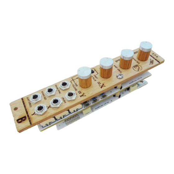
Page 9: Enclosure Assembly
ENCLOSURE ASSEMBLY Again we want to make sure that all the c omponents are properly aligned with the front panel, so take the standoff and place it in the opening. Check that all the components came through and then screw the wooden front panel with the second hex screw. Also secure the jacks to the panel with the washers and the nuts. IMPORTANT Don’t tighten the screws and jack washers too much as you may damage them! ... - Page 10 The switch s hould have some space off the board, or else they won’t come through the panel, like in the image below. Make sure that everything is nicely aligned and solder the components. ...
- Page 11 Congratulations! You have made it through, now just connect the bottom board, add the knobs, connect the expansion to the main board and you are ready to enjoy your new module. Before you connect anything, make sure that your system is disconnected from power. Also double check the polarity of the ribbon cable, the red cable should match the 12V rail both on the module and on the bus board! And make sure that connection cable on both modules are in the same side! ...
-
Page 12: Troubleshooting
TROUBLESHOOTING did you plug it in? RELEASES ● 1.0 – Original release. ...
Need help?
Do you have a question about the SPA V1.0 and is the answer not in the manual?
Questions and answers