Table of Contents
Advertisement
Quick Links
Advertisement
Table of Contents

Subscribe to Our Youtube Channel
Related Manuals for Phason Plus Touch Series


Summary of Contents for Phason Plus Touch Series
- Page 2 Copyright Phason Inc. Printed in Canada All rights reserved. 34340001...
-
Page 3: Table Of Contents
Connecting variable heating or cooling equipment ................18 Using three-phase power ........................19 Connecting an alarm system ....................... 20 Connecting Phason 3K temperature sensors ..................21 Connecting DOL sensors ........................22 Connecting the power source ......................23 Finishing the installation .......................... 23 Chapter 3: Configuring your Plus Touch ................ - Page 4 Chapter 4: Programming the Plus Touch ................. 37 Before you program the Plus Touch ....................... 37 Programming zone settings ........................38 Programming the master set point ...................... 38 Programming growth curves ....................... 39 Programming minimum ventilation curves ..................41 Programming modifiers ........................43 Programming alarms ...........................
-
Page 5: Chapter 1: Introducing Plus Touch
Chapter 1: Introducing Plus Touch Getting to know Plus Touch brings a wealth of features that make it a powerful, versatile, and easy to use control. Plus Touch Plus Touch has two variable AC stages and six relays to automatically control temperatures by operating ventilation, heating, and cooling equipment according to your programmed settings. -
Page 6: Features
Relay staggering for distributing startup loads One alarm relay (for external siren or alarm system) Sensor inputs: 5× Phason 3K Temperature 1× DOL-114 Temperature and Humidity 3× inputs for compatible DOL sensors Intuitive user experience ... -
Page 7: Becoming Familiar With Plus Touch
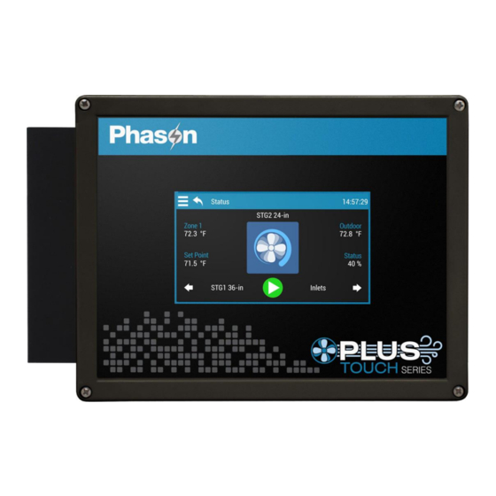
Becoming familiar with Plus Touch Becoming familiar with Plus Touch The Status screen is the “home” screen. The status screen is where you can find all basic information at a quick glance. From the status screen, you can easily access configuration, settings, and more by pressing the menu in the top left corner. -
Page 8: Unlocking The Screen
Chapter 1: Introducing Plus Touch Menu layout MANUAL OVERRIDE SETTINGS CONFIGURATION ADMINISTR ATION SCREEN LOCK ABOUT Staged ventilation Equipment Configuring lock Relay stages Sensors Restart control Ventilation curve Hysteresis Restore defaults Actuator settings Units Show diagnostics Variable stages Duty cycles Relay stagger Saved to USB Curtain settings... -
Page 9: Chapter 2: Installing The Plus Touch
Surge suppression devices offer some protection from power surges. Because it is not possible to internally protect this product completely from the effects of power surges and other transients, Phason that you install external surge suppression devices. For specific highly recommend recommendations, see your electrical contractor. -
Page 10: Reducing Electrical Noise Using Filters
Some power contactors include snubber filters. For more information, read on page 11. Using power contactors to increase the capacity of relays For more information about snubber filters or other Phason accessories, see your dealer or visit www.phason.ca... -
Page 11: Electrical Ratings
Make sure the motor/equipment connected to the variable stage does not draw more than 7 FLA. Using power contactors to increase the capacity of relays Phason’s Manual Override Box ( ) has four 240-volt power contactors that allow you to model MOB-4 increase the load handling capability of control relays. -
Page 12: Bottom Layout
Actuator feedback terminals (ACT1 and ACT2) – connect the feedback from the actuators to these is terminals. Phason 3K temperature sensor terminals (TEMP1 to TEMP4) – connect the sensors to these terminals. Display cable – make sure the ribbon cable from the display is properly connected to the socket. -
Page 13: Cover Layout
Cover layout USB – connect a USB drive when saving or loading settings, or updating firmware. OUTDOOR – connect a Phason 3K Temperature Sensor for measuring outdoor temperature. +5V – can provide +5 VDC DOL (AUX1 to AUX3) – connect DOL 19 Carbon Dioxide or DOL 53 Ammonia Sensors. -
Page 14: Mounting The Plus Touch
Chapter 2: Installing the Plus Touch Mounting the Plus Touch 1. Select a location for the Plus Touch. Make sure you have enough cable and wire to reach all the equipment (fans, heaters, misters, curtains, etc.) that you want to control. 2. - Page 15 Connecting equipment to the Plus Touch Actuators can be connected to relay pairs 1 and 2 or 3 and 4 only. Actuators cannot be connected to any other combination of relays. For example, you cannot connect an actuator to relays 1 and 3. In Plus Touch, actuators are considered “inlets with feedback”.
-
Page 16: Connecting Curtain Machines
Chapter 2: Installing the Plus Touch To connect actuators Connect actuators to the Plus Touch as shown below. Refer to your actuator’s installation guide for information about its power supply requirements. AC-powered actuators DC-powered actuators Connecting curtain machines Curtains are usually controlled by equipment called curtain machines (sometimes referred to as winches). -
Page 17: Connecting Cooling, Heating, And Duty Cycle Equipment To Relays
Connecting equipment to the Plus Touch To connect curtain machines Connect curtain machines to the Plus Touch as shown. Connecting cooling, heating, and duty cycle equipment to relays Heating or cooling equipment includes electric heaters, furnaces, single-speed fans, and any other equipment that is either on or off. -
Page 18: Connecting Variable Heating Or Cooling Equipment
Chapter 2: Installing the Plus Touch To connect equipment to relays Connect equipment as shown below. Gas-fired furnace or brooder All other single-speed heating or cooling elements Connecting variable heating or cooling equipment Variable cooling equipment includes equipment such as variable-speed fans. Variable heating equipment includes equipment such as heat mats and heat lamps. -
Page 19: Using Three-Phase Power
Connecting equipment to the Plus Touch To connect equipment to variable stages Connect variable heating or cooling equipment to the Plus Touch as shown below. Using three-phase power If you are connecting the Plus Touch to a three-phase system, make sure to connect the control power and the variable cooling equipment to the same phase. -
Page 20: Connecting An Alarm System
Chapter 2: Installing the Plus Touch Connecting an alarm system You can connect an alarm system to the Plus Touch’ alarm terminal. An alarm system can be a siren, alarm panel, or auto-dialer. Read your system’s installation guide for installation instructions and information about the type of system: . -
Page 21: Connecting Phason 3K Temperature Sensors
Phason’s standard 3K temperature sensors to these terminals. All connected and enabled probes are averaged to provide a more balanced temperature reading in the zone. You can also connect a Phason 3K temperature sensor to the OUTDOOR terminal for monitoring outdoor temperatures. -
Page 22: Connecting Dol Sensors
Chapter 2: Installing the Plus Touch Connecting DOL sensors Plus Touch gives you the ability to connect DOL 114 temperature and humidity, DOL 19 carbon dioxide, and DOL 53 ammonia sensors. Connecting the additional sensors gives you the ability to use modifiers that allow you to override settings when certain conditions are met, such as when carbon dioxide levels are too high. -
Page 23: Connecting The Power Source
Finishing the installation Connecting the power source Before connecting the incoming power, switch OFF the power at the source. Do not switch ON the power until you have finished all wiring and verified all equipment is properly connected and free of obstructions. Before connecting the power, set the voltage selection switch to the correct ... - Page 24 Chapter 2: Installing the Plus Touch 5. Switch on the power to the Plus Touch. When you switch on the power to the Plus Touch, the display should show the status screen. If the display does not come on, go back to step 1. If the display shows an alarm message, read on page 45.
-
Page 25: Chapter 3: Configuring Your Plus Touch
Chapter 3: Configuring your Plus Touch Chapter 3 explains how to configure the Plus Touch. Configuring the Plus Touch includes telling it which equipment is connected to each terminal. below What you need to know before configuring on page 26 Configuring the main control functions ... -
Page 26: Configuring The Main Control Functions
Chapter 3: Configuring your Plus Touch Configuration checklist Because some items need to be configured before others, we recommend configuring the Plus Touch in following order. Configuring main control functions Setting the clock Selecting the units of measure Configuring hysteresis Configuring relay stagger Configuring alarm silencing Configuring the zone control mode... -
Page 27: Selecting The Units Of Measure
Configuring the main control functions To set the clock 1. Press the and then Menu Configuration 2. Press Date and Time 3. To switch between 12 and 24 formats, select or deselect 24-Hour Time 4. Press the arrows to adjust the date and time. Down 4. -
Page 28: Configuring Relay Stagger
Chapter 3: Configuring your Plus Touch To configure hysteresis 1. Press the and then Menu Configuration 2. Press Hysteresis 3. Press the arrows to adjust the hysteresis value. Down 4. Press Save Configuring relay stagger Relay stagger prevents several relays from switching on at the same time by offsetting each relay when the control starts. -
Page 29: Configuring The Zone Control Mode
Configuring the main control functions To configure alarm silencing 1. Press the and then Menu Configuration 2. Press Alarm Silencing 3. Press the arrows to change the alarm silencing variation. Down 4. Press Save Configuring the zone control mode There are two zone control modes: staged and merged. Staged mode Staged mode is the traditional ventilation mode that uses “stages”... -
Page 30: Configuring Sensor Inputs
Plus Touch supports the following sensors connected to the specified inputs. Other sensors are not supported. Input Location Sensor types Zone control Influencer TEMP1 to 4 Bottom Phason 3K TEMP TEMP – YES Cover DOL114 Temperature and Humidity Sensor HUM – NO AUX1 DOL19 Carbon Dioxide (CO2) AUX2... - Page 31 Configuring sensor inputs Temperature averaging and zone control If you have more than one temperature sensor assigned to control a zone, Plus Touch automatically averages the temperature readings it receives. Temperature averaging provides a more balanced, overall temperature for a zone. If there are no functioning temperature sensors, Plus Touch controls the ...
-
Page 32: Configuring Equipment
Chapter 3: Configuring your Plus Touch Configuring equipment Configuring variable stages The Plus Touch has two variable AC stages ( ) to control equipment using gradually VAC 1 VAC 2 increasing or decreasing voltage. Variable stages can be cooling or heating. : the stage controls cooling equipment, such as a variable speed fan. -
Page 33: Configuring Relays
Configuring equipment Configuring relays Plus Touch has six relays that can be configured for any of the following functions: : the relay is always open/off. This is the default. Not used : the relay controls cooling equipment, such as a fan, and switches on when temperatures Cooling ... -
Page 34: Calibrating Inlet Actuators
Chapter 3: Configuring your Plus Touch To configure relays for inlets 1. Press the and then Menu Configuration 2. Press Equipment 3. Scroll to and then press the relay you want to configure. The Equipment Configuration screen displays. 4. To rename the inlet, press Rename 5. -
Page 35: Configuring Relays For Heating, Cooling, Or Duty Cycle
Configuring equipment To calibrate inlet actuators 1. At the Status screen, press the widget for the actuator you want to calibrate. 2. Press Calibrate 3. Press to start calibration or to cancel. If you started calibration, the actuator should open all the way and then close all the way. If calibration is successful, the actuator will move into position according to its settings. - Page 36 Chapter 3: Configuring your Plus Touch To configure relays for heating, cooling, or duty cycle 1. Press the and then Menu Configuration 2. Press Equipment 3. Scroll to and then press relay you want to configure. The Output Configuration screen displays. 4.
-
Page 37: Chapter 4: Programming The Plus Touch
Chapter 4: Programming the Plus Touch on page 38 Programming zone settings on page 48 Programming equipment settings Before you program the Plus Touch Programming your Plus Touch means “telling” the equipment what you want it to do and when you want it done. -
Page 38: Programming Zone Settings
Chapter 4: Programming the Plus Touch Before you program the Plus Touch, make sure: It has power All equipment has been properly connected to the correct terminals You know which equipment is connected to variable stages, relays, and sensor inputs ... -
Page 39: Programming Growth Curves
Programming zone settings To program the master set point 1. Press the and then Menu Settings 2. Press Master Set Point 3. Below Zone, press the arrow to choose the zone. Left Right 4. Below Set Point, press the arrows to set the master set point for the zone. Down 5. - Page 40 Chapter 4: Programming the Plus Touch For example, in the table on the right, the duration of Step Temperature (°F) Duration (days) step 2 is 10 days. The difference between the starting 88.0 set point (86.5°F) and the starting set point for the 86.5 next step (85°F) is 1.5°F.
-
Page 41: Programming Minimum Ventilation Curves
Programming zone settings To program growth curves 1. Press the and then Menu Settings 2. Press Staged Ventilation 3. Press Ventilation Curve 4. Below Zone, press the arrow to choose the zone. Left Right 5. Below Step Start Day, press the arrows to set the start day for each step. - Page 42 Chapter 4: Programming the Plus Touch The minimum ventilation curve affects only the first variable stage that is configured as cooling for the zone. The following examples show which variable stage would be affected by the minimum ventilation curve in different situations. Example 1 Example 2 Example 3...
-
Page 43: Programming Modifiers
Programming zone settings To change the current day 1. Press the and then Menu Settings 2. Press Staged Ventilation 3. Press Ventilation Curve 4. Below Current Day, press the arrow to change the day. Left Right 5. When finished, press Save Programming modifiers Modifiers, sometimes called influencers, allow you to override equipment settings when certain... - Page 44 Chapter 4: Programming the Plus Touch must meet two conditions before setting or adjusting the output. For And With Next modifiers example, “When the temperature is over 80°F and the humidity is over 90%, switch on a fan.” To view modifiers Press the left or right arrow beside Output to view or choose which variable stage or relay you ...
-
Page 45: Programming Alarms
Programming zone settings 7. Press the arrows below Starting Output to set the output at the beginning of the Down influence range, and Ending Output to set the output at the end of the influence range. 8. When finished, press Save To remove modifiers 1. - Page 46 Chapter 4: Programming the Plus Touch You set the compensation offset and the high maximum values. Plus Touch adds the compensation offset to the outdoor temperature to create a new setting called the compensated high alarm. The compensated high alarm becomes the new temperature limit, up until the high alarm maximum. When the zone temperature is higher than the compensated high alarm, there is an alarm condition.
- Page 47 Programming zone settings To enable or disable alarms 1. Press the and then Menu Settings 2. Press Alarms 3. Below Zone, press the arrow to choose the zone, sensor, or equipment you want. Left Right 4. To enable or disable an alarm, press the box beside the one you want to enable.
-
Page 48: Programming Equipment Settings
Chapter 4: Programming the Plus Touch Programming equipment settings Programming the stages means entering the settings such as set points, idle speeds, ON/OFF times and durations, and so on. Staged ventilation Merged ventilation Heating Variable stages (on page 49) Merged (below) Variable stages (on page 51) ... -
Page 49: Programming Variable Cooling Stages
Programming equipment settings You must have the zone configured for merged ventilation to program it. You can use a growth curve in merged mode, but you cannot use a minimum ventilation curve. The set points for merged ventilation cannot be lower than the master set point ... - Page 50 Chapter 4: Programming the Plus Touch How variable stage cooling works When the temperature is below the temperature, the fan is off. idle range When the temperature reaches the temperature, the fan runs at the . The idle range idle speed ...
-
Page 51: Programming Variable Heating Stages
Programming equipment settings To program variable stages for ventilation 1. Press the and then Menu Settings 2. Press Staged Ventilation 3. Press Variable Stages 4. Press stage you want to program. 5. Press the arrows to each of the settings. Down 6. - Page 52 Chapter 4: Programming the Plus Touch Heat output Minimum heat The heater is off. Heat cutoff The heater is at its minimum heat output. Set point Heater output increases as the temperature drops, or decreases as the temperature rises. Differential The heater is at full output.
-
Page 53: Programming Inlet Actuators
Programming equipment settings Programming inlet actuators Before programming the inlet actuator relays, make sure you have properly configured the relays and calibrated the actuators. For more information, read Configuring relays for inlet actuators or on page 33 and on page 34. curtains Calibrating inlet actuators How inlets work... -
Page 54: Programming Curtain Control Relays
Chapter 4: Programming the Plus Touch To program inlet actuators 1. Press the and then Menu Settings 2. Press Staged Ventilation 3. Press Actuators 4. Press the actuator and stage you want to program. It is best to program them in order, from minimum to 5. - Page 55 Programming equipment settings Time (duration) Open idle duration (02:00 mm:ss) After the curtain opens for the open run duration, it holds its position for the open idle duration. Open run duration (00:30 mm:ss) If the temperature rises above the idle band, the curtain opens for this duration.
-
Page 56: Programming Relay Stages
Chapter 4: Programming the Plus Touch 4. Press the curtain you want to program. The common settings (set point and idle band) and the closing settings (run duration and idle duration) display. 5. Press the arrows to adjust each of the common and closing settings. Down 6. -
Page 57: Programming Duty Cycles
Programming equipment settings Programming duty cycles A duty cycle switches equipment on and then off for specific durations, consistently repeating the process. ON duration ON duration All on durations are the same OFF duration OFF duration All off durations are the same There are three types of duty cycles: , and temperature based... - Page 58 Chapter 4: Programming the Plus Touch To program cooling duty cycles 1. Press the and then Menu Settings 2. Press Staged Ventilation 3. Press Duty Cycles 4. Press the relay you want to program. 5. Press type of duty cycle you want. The displayed settings change depending which duty cycle you select.
-
Page 59: Using Settings Groups
Using settings groups Using settings groups Settings groups allow you to have different configuration and settings for different situations. For example, you can have a settings group for each of the different seasons. When you transition from one season to another, you can switch to another group without having to reprogram the control each time. - Page 60 Chapter 4: Programming the Plus Touch To copy settings from one group to another 1. Scroll to the group you want to copy the settings from. 2. Press Confirm by pressing Copy. 3. Scroll to the group you want to copy the settings to. 4.
-
Page 61: Chapter 5: Monitoring And Maintaining Your Plus Touch
Chapter 5: Monitoring and maintaining your Plus Touch below Monitoring the Status screen on page 63 Testing sensors and equipment on page 65 Using screen lock security on page 66 Servicing and maintaining your Plus Touch Monitoring the Status screen The Status screen displays information about each sensor and piece of equipment. -
Page 62: Widgets
Chapter 5: Monitoring and maintaining your Plus Touch Status indicators Light gray Dark gray A sensor in normal status Equipment that is off Blue Orange Ventilation equipment that is on Heating equipment that is on Green Purple Equipment or sensor that is in manual override Equipment that is affected by a modifier Equipment or sensor that has an alarm condition Equipment icons... -
Page 63: Acknowledging Alarms
Testing sensors and equipment Acknowledging alarms An alarm occurs if an enabled alarm condition is present for longer than the minimum duration of one minute. The one minute minimum duration prevents alarms from occurring when the temperature rises or falls or just a few seconds. The exceptions to the one minute minimum are the actuator jam alarms. -
Page 64: Testing A Zone's Sensors And Equipment
Chapter 5: Monitoring and maintaining your Plus Touch 4. Press the arrows to adjust the state, output, or reading. Down Plus Touch automatically puts the item to manual override. 5. When finished, press to return to automatic mode. Auto Option 2 – single or multiple sensors or equipment 1. -
Page 65: Using Screen Lock Security
To enable or disable screen lock or the locked override option, press the Enabled button for that option. Disabled 3. When finished, press Save If the PIN has been forgotten and nobody can access the control, contact Phason technical support. For contact information, see page 93. -
Page 66: Servicing And Maintaining Your Plus Touch
Chapter 5: Monitoring and maintaining your Plus Touch Servicing and maintaining your Plus Touch Restoring the factory defaults The Plus Touch leaves the factory with default configuration and settings. Resetting the Plus Touch erases all the configuration and settings you programmed and restores them to what they were when the control left the factory. -
Page 67: Displaying The Firmware Version
Android have version numbers, the Plus Touch firmware has a version number. If you need to contact Phason Customer Support about the Plus Touch, you might need to provide them with the firmware version of your control. For more information about technical support, read at the back of the manual. -
Page 68: Updating The Firmware
Chapter 5: Monitoring and maintaining your Plus Touch Updating the firmware Phason constantly improves and adds new features to their products. You can upgrade the firmware in your Plus Touch as these features become available. The update takes about 20 to 30 seconds. -
Page 69: Replacement Kits And Optional Accessories
Servicing and maintaining your Plus Touch If there is a problem during the update, leave the USB drive connected and follow these steps. Switch off the power to the Plus Touch for 10 seconds, and then switch it on again. The control should automatically update when it restarts. Replacement kits and optional accessories Replacement kits and several optional, convenient accessories are available to enhance and extend the Plus Touch. - Page 70 Additional sensors Phason 3K probes and extension cable Phason 3K temperature probes monitor temperatures ranging from –49 to 122°F (-45 to 50°C). The probes are available in 1, 6, 30, 75, or 150-foot cable lengths and can extended up to 500. Extension cable is available in 500-foot lengths.
- Page 71 Servicing and maintaining your Plus Touch Accessories Power contactors The Manual Override Box ( ) increases the load handling model MOB-4 capability of relays and provides an external disconnect. The MOB-4 includes four 240 V power contactor relays with AUTO-OFF-MANUAL switches and snubber filters.
-
Page 72: Appendixes
Appendixes This section contains reference information that is useful when installing, configuring, setting up, or troubleshooting the Plus Touch. below Appendix A: Troubleshooting on page 76 Appendix B: Factory defaults on page 77 Appendix C: Installation worksheet on page 79 Appendix D: Configuration worksheets ... - Page 73 For more information, read Configuring sensor inputs on page 30. Unusually high or low A non-Phason probe is connected Remove the probe and then install a Phason temperature readings to TEMP 1/2/3/4 probe. The extension cable connected to Check the extension cable connection.
- Page 74 Appendixes Problem Possible causes Possible solutions Circuit breaker open Reset the breaker. Variable speed 1 or variable The hysteresis is not high enough. Adjust the hysteresis setting or overlap the speed 2 fan switches on, runs The outside temperature is rising variable speed 1 or variable speed 2 fan at full speed, and then turns off.
-
Page 75: Determining Correct Actuator Feedback Wiring
Appendix A: Troubleshooting Determining correct actuator feedback wiring After installing a new actuator or potentiometer, or due to age-related potentiometer wear, the actuator might not move correctly. Common symptoms include: The actuator oscillating back and forth The actuator not traveling the full stroke during calibration ... -
Page 76: Appendix B: Factory Defaults
Appendixes Appendix B: Factory defaults The Plus Touch leaves the factory with default configuration and settings. Resetting the Plus Touch erases all the configuration and settings you programmed and restores them to what they were when the control left the factory. For more information, read on page 66. -
Page 77: Appendix C: Installation Worksheet
Appendix C: Installation worksheet Appendix C: Installation worksheet Use the when you fill in the Installation worksheet Configuration worksheets (starting on page 79). Input power 120/230 VAC, 50/60 Hz Variable AC stages (VAC 1, VAC 2) 10 A at 120/230 VAC, general-purpose (resistive) 7 FLA at 120/230 VAC, PSC motor 1/2 HP at 120 VAC, 1 HP at 230 VAC, PSC motor 15 A, 250 VAC ABC-type ceramic... - Page 78 VDC 2 VDC 3 VDC 4 Phason 3K Temperature sensor only DOL 114 Temperature and Humidity sensor only DOL 19 Carbon Dioxide or DOL 53 Ammonia sensor only Requires optional Variable DC Module, model VDC-4...
-
Page 79: Appendix D: Configuration Worksheets
Appendix D: Configuration worksheets Appendix D: Configuration worksheets Use the on page 77 when completing the configuration Installation Worksheet worksheets. Main control function worksheet Item Description Configuration Zone function There are two ventilation modes, staged and VentGrid Zone 1: Staged Merged merged. -
Page 80: Variable Stage Configuration Worksheet
Appendixes Variable stage configuration worksheet For each variable, fill in the information as shown in the example at the top. For configuration information, read on page 32. Configuring variable stages Variable Description Zone Cool Motor curve Deicing Heat Example: VAC 1 Stage 1 fan ... -
Page 81: Relay Configuration Worksheet
Appendix D: Configuration worksheets Relay configuration worksheet For each relay, fill in the information as shown in the example table. For configuration information, read on page 33. Configuring relays Relay Description Inlet open Inlet close 36-inch fan Electric heat ... -
Page 82: Appendix E: Settings Worksheets
Appendixes Appendix E: Settings worksheets Settings worksheets are for you to use when programming the Plus Touch settings. Each worksheet contains a brief explanation of the information required. For more information about programming the Plus Touch, see on page 37. Chapter 4: Programming the Plus Touch Growth curve worksheet A growth curve automatically adjusts the temperature set points over time to control the... -
Page 83: Variable Stage Settings Worksheet
Appendix E: Settings worksheets Variable stage settings worksheet For information about programming variable stage settings, read Programming variable cooling on page 49, or on page 51. stages Programming variable heating stages Idle speed / Idle range / Variable Minimum heat Heat cutoff Set point Differential... - Page 84 Appendixes Setting Actuator 1 Actuator 2 Description Minimum Set point The temperature below which the actuator is closed The percentage the actuator is open when the temperature is at Position or above the minimum set point Stage 1 Set point The temperature at which the actuator starts opening for stage 1 Differential...
-
Page 85: Curtain Worksheet
Appendix E: Settings worksheets Curtain worksheet Curtains control the temperature by adjusting the air flow into the facility. Each curtain has six settings. – the temperature at which the curtain holds its position. Set point – the buffer around the set point within which the curtains hold their position. Idle band ... -
Page 86: Alarm Settings Worksheet
Appendixes Duty cycle Relay Type Set point Type ON duration OFF duration Relay 5 Heat Ventilation Temperature 01:30 03:00 Relay 1 Heat Ventilation Relay 2 Heat Ventilation Relay 3 Heat Ventilation Relay 4 Heat Ventilation Relay 5 Heat Ventilation Relay 6 Heat Ventilation ... -
Page 87: Appendix F: Motor Curves
Appendix F: Motor curves Appendix F: Motor curves Motor curves provide a way to proportionally increase or decrease speed, regardless of motor manufacturer. For example, a Multifan motor might require 130 VAC to run at 50% RPM, while a Marathon motor might need 100 VAC to run at 50% RPM. Without a motor curve, the Multifan motor would run at a slower RPM than the Marathon motor at the same settings. - Page 88 Appendixes Manufacturer Diameter Model Specifications Recommended curve (inches) 0.53 HP, 1700 RPM 0.63 HP, 1700 RPM Franklin 1/6 HP, 3450 RPM Leeson 1/4 HP, 1625 RPM 1/3 HP, 1625 RPM 1/3 HP, 1140 RPM 1/2 HP, 1625 RPM 3/4 HP, 1625 RPM Magnetek 1/6 HP, 3300 RPM 1/6 HP, 1725 RPM...
-
Page 89: Index
Index relays ............. 33–34 sensors ..........28–29 3K sensors time ............24–25 configuring ........... 28–29 units of measure ......... 25 connecting ..........19 variable stages ..........30 zone control mode ........ 27–28 connect accessories ............. 69 3K sensors ..........19 acknowledge alarms ........ - Page 90 ........... 61–62 growth curve ........27–28, 37–39 parts..............67 home screen ..........59–60 Phason 3K sensor terminals ......10 humidity sensor ...... See DOL sensors PINs ........... See screen lock hysteresis ..........25–26 potentiometer feedback ......10, 13 power contactors ........
- Page 91 programming checklist ........35 three-phase power .......... 17 time ............24–25 troubleshooting ......... 70–72 ratings ............... 9 relay stagger ........... 26 relay terminals ..........10 units of measure ..........25 repair kits ............67 unlock screen ..........63 restore factory defaults ......58, 64 update firmware ........
- Page 92 Limited warranty This warranty applies only to the Phason Plus Touch (PLUS-TOUCH). If you need warranty service, return the product and original proof of purchase to your dealer. Phason Inc. (Phason) warrants the PLUS-TOUCH subject to the following terms and conditions.
- Page 93 Service and technical support Phason will be happy to answer all technical questions that will help you use the Plus Touch. Before contacting Phason, check the following: Read this manual for information about the feature with which you are having trouble.
Need help?
Do you have a question about the Plus Touch Series and is the answer not in the manual?
Questions and answers