Table of Contents
Advertisement
Quick Links
Advertisement
Chapters
Table of Contents

Subscribe to Our Youtube Channel
Related Manuals for Phason AEC-2


Summary of Contents for Phason AEC-2
- Page 1 Automatic Environment Control AEC-2 user manual...
- Page 2 © 2009, Phason Inc. All rights reserved. Printed in Canada. 10140404 2009-09-23...
- Page 3 Phason Inc. (Phason) warrants this product subject to the following terms and conditions. This warranty is valid only to the original purchaser of the AEC-2, for two years from the manufacturing date. The manufacturing date is stated in the first eight digits of the serial number in the form year-month-day.
- Page 4 Service and technical support Your dealer will be happy to answer all technical questions that will help you use the AEC-2 Before contacting your dealer or Phason, check the following: Read this manual for information about the feature with which you are having trouble.
-
Page 5: Table Of Contents
Features of the AEC-2 ......................1 Getting started ........................2 AEC-2 electrical ratings ....................4 Equipment list ......................... 5 Getting to know the AEC-2 ....................6 Definition of terms ......................7 Adjusting the AEC-2 ......................8 Selecting a new operating program ................. 8 Changing parameter settings ................... -
Page 7: Features Of The Aec-2
It connects to a variable speed fan, a combination of secondary fans and heaters and an alarm system. When operating, the AEC-2 measures and displays the room temperature. While monitoring the temperature it controls the connected ventilation and heating equipment according to the programmed settings to keep the temperature at the desired point. -
Page 8: Getting Started
The Getting Started section will step you through the installation and configuration of your AEC-2. The following steps refer to other sections of this user's guide for additional information. For this reason, it is not necessary to read through the entire document from front to back, but rather in the order that the information is needed. - Page 9 AEC-2 user manual SETTING UP STEP Read through the ADJUSTING THE AEC-2 section starting on page 8 and get familiar with the programming procedures. Configure the AEC-2 according to the type of equipment connected. Mark the changes in the Blank Program Tables in Appendix D.
-
Page 10: Aec-2 Electrical Ratings
AEC-2 user manual Phason AEC-2 electrical ratings Incoming power 120/230 VAC, 50/60 Hz Variable stage 12.5 A at 120/230 VAC, general-purpose (resistive) 9 FLA at 120/230 VAC, PSC motor 1/2 HP at 120 VAC, 1 HP at 230 VAC, PSC motor... -
Page 11: Equipment List
Phason AEC-2 user manual Equipment list Make and Model # of fan(s): Max. Total Current Draw of fan(s): Variable Speed Maximum 12.5 A. See the Warning Stage 1 section in Appendix A. Operating Voltage: Make and Model # of fan/heater: Cool / Heat Max. -
Page 12: Getting To Know The Aec-2
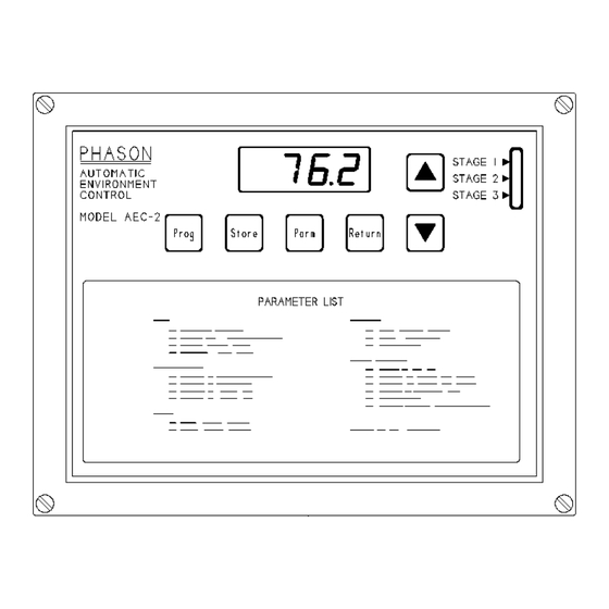
AEC-2 user manual Phason Getting to know the AEC-2 PROGRAM button - used to select the UP button -used to increase the value of a desired operating program. parameter. STORE button - used to save selected programs and parameter settings in STAGE 1 indicator light. -
Page 13: Definition Of Terms
Phason AEC-2 user manual Definition of terms NORMAL OPERATION The AEC-2 is in normal operation when it is displaying the room temperature. When alerts occur, the display will alternately flash the alert message and the room temperature. PROGRAMS Programs consist of Main, Differential, Alerts and General parameters. The AEC-2 has eight programs which can be selected and reprogrammed by the user. -
Page 14: Adjusting The Aec-2
Selecting a new operating program As livestock matures, often a change in the room climate is needed. The AEC-2 has eight different programs in memory for eight different climate settings. Any one of the programs can be chosen as the operating program. -
Page 15: Changing Parameter Settings
Phason AEC-2 user manual Changing parameter settings Follow the steps below to view and/or edit the parameters in any program. After the parameters have been edited, the changes should be marked in the Blank Program Tables in Appendix D for future reference. - Page 16 RETURN again to return to normal operation. NOTE: If the AEC-2 is left displaying a parameter it will revert back to normal operation in 1 minute automatically. If STORE was not pressed the displayed parameter will change back to its previous value.
-
Page 17: Setup Parameters
It is important that the Configuration decal, included with the AEC-2, is marked correctly and affixed to the side of the AEC-2 when the setup parameters have been programmed. The Configuration decal provides a handy reference when you need to check the mode of operation of the staged outputs. - Page 18 AEC-2 user manual Phason Selecting a Parameter to Edit The parameters are stored in a table in memory which is similar to the Factory Program Table on page 22. Any parameter in any program can be edited when memory protection has been turned off. Follow these procedures when editing parameters to become more efficient.
-
Page 19: Reloading The Factory Programs
When the factory programs are reloaded, all of the existing programs including the setup parameters will be replaced. The AEC-2 will begin with program A as the operating program. The programs and most importantly the setup parameters will need to be reprogrammed for the equipment that is connected. Pay close attention to the configuration of Stages 2 and 3. -
Page 20: Aec-2 Operation
Figure 2 shows the operation of each stage of the AEC-2. This particular diagram shows when the stages will turn on and off if the AEC-2 is operating according to the factory settings in program C. Some settings are listed here but the entire factory program table can be found on page 22. The circled numbers correspond to the parameter numbers. - Page 21 Phason AEC-2 user manual Figure 2: Factory program C operation diagram 10140404...
-
Page 22: Cutback Speed Operation
Cutback-speed operation Figure 3 shows the operation of each stage of the AEC-2. This diagram is the same as the one shown in Figure 2 with one exception; parameter 3 has been changed from 99 to 20, (see the parameter settings below). - Page 23 Phason AEC-2 user manual Figure 3: Cutback speed operation diagram 10140404...
-
Page 24: Parameter Descriptions
AEC-2 user manual Phason Parameter descriptions MAIN PARAMETERS MEMORY PROTECTION [On/Off] - ensures parameters are not changed by accident. Memory protect must be turned off every time the parameters are edited. The memory protect parameter cannot be stored and is turned on automatically when the control is returned to normal operation. - Page 25 Ventilation may be turned OFF when a room is vacant to conserve energy. When it is turned OFF the AEC-2 will display V°FF. DO NOT use this to shut down fans to work on the fans or electrical wiring. Ensure the breakers are turned off.
- Page 26 17 STAGE 1 POWER FACTOR COMPENSATION [0.5 - 2.5] - This is set at the factory to 1.0 and should only be adjusted if the Stage 1 variable speed fan does not operate properly with the AEC-2. 18 HYSTERESIS [0.5 - 2.5°F, 0.3 - 1.4°C] - This is the number of degrees of difference between the turn-on point and turn-off point for all stages.
-
Page 27: Parameter Ranges
Phason AEC-2 user manual Parameter ranges RANGES PARAMETERS °F °C MAIN Memory Protection ON / OFF Temp Set (Start P-Band) 32.0 to 110.0 0.0 to 43.3 Stage 1 Min Vent Min Idle (parm #16) to 99 % Cutback Speed Min Idle (parm #16) to 99 %... -
Page 28: Factory Programs
AEC-2 user manual Phason Factory programs The AEC-2 is preprogrammed with the factory settings as shown below. See the GETTING TO KNOW THE AEC-2 section for instructions for selecting a program. Select the most useful program and make changes where necessary. -
Page 29: Methods Of Use
Methods of use Programs The AEC-2 has eight programs from which one can be selected as the operating program. To take advantage of the programs, adjust them for different climate settings. They could be used for different kinds of livestock or used at different stages of maturity of the particular livestock. Time is saved by simply changing the program, instead of adjusting every parameter. -
Page 30: Alert Messages
AEC-2 user manual Phason Alert messages ALERT DESCRIPTION Error - an incorrect key has been pressed Alert High Temperature - temperature is above the high temp alert setting Alert Low Temperature - temperature is below the low temp alert setting... - Page 31 Another way to clear the alert is downloading the factory programs. This will reset all the parameters to the factory settings and then they must be programmed to the desired settings again. Consult your dealer or Phason for information to prevent this problem from happening again.
-
Page 32: Care And Maintenance
AEC-2 user manual Phason Care and maintenance Moisture will not cause a problem with the control if the proper care is taken in installation. The control's enclosure is made of fire retardant plastic and is sealed with a rubber gasket. The sensor entry is sealed with a liquid tight cable connector. -
Page 33: Power Factor Correction
Phason AEC-2 user manual Power factor correction Adjusting the P-Band to correct for a particular power factor may improve your ventilation system's performance. Power factor correction is generally unnecessary and there is no danger of damage being done to the control or motor if it is not done. As a result of different power factors between the many makes and models of fan motors, the actual P-Band may be less then the P-Band setting displayed by the control. - Page 34 AEC-2 user manual Phason 2009-09-23...
-
Page 35: Appendix A - Wiring Diagrams
Phason AEC-2 user manual Appendix A - Wiring diagrams Installation overview ......................A-2 General warnings ....................... A-3 Mounting instructions ......................A-4 Grounding and sealing ....................... A-4 230 VAC control and stage 1 .................... A-5 120 VAC control and stage 1 .................... A-5 Temperature sensor ...................... -
Page 36: Installation Overview
AEC-2 user manual Phason Installation overview ALERT RELAY STAGE 3 STAGE 2 VARIABLE SPEED TEMP SENSOR Page Pages Pages Page Pages A-10 A-10 Wiring diagrams and instructions for the different stages are located on the pages listed above. First read the General Warnings and Mounting Instructions sections, then follow the instructions given for each stage. -
Page 37: General Warnings
100% free of defects. Even reliable products may experience occasional failures, and this possibility should be recognized by the User. If Phason products are used in a life support ventilation system where failure could result in loss or injury, the user should provide adequate back-up ventilation, supplementary natural ventilation or an independent failure alarm system. -
Page 38: Mounting Instructions
Mounting instructions To mount the AEC-2, remove the four screws in the front cover and lift off the cover. The cover can be unplugged from the bottom to make wiring easier. Mount the box to the wall with the four wood screws provided with the control. -
Page 39: 230 Vac Control And Stage 1
Phason AEC-2 user manual 230 VAC control and stage 1 Connect the power mains to the BLACK and WHITE wires. Connect the variable speed fan to the BLUE and WHITE wires. A - Set voltage selector switch to the 230 VAC position. -
Page 40: Temperature Sensor
To take advantage of this option, you must connect four temperature sensors to the unit. To manually extend the sensor, follow the instructions on page A-7. A) The AEC-2 can operate with one or four probes connected. 2009-09-23... -
Page 41: Manually Extending Sensor
Phason AEC-2 user manual Manually extending the sensor To extend the sensor, use 2 wire 18 or 20 AWG jacketed cable. To splice two wires together follow the steps below and refer to the diagram. A) Slide pieces of heat shrink tubing on the wire ends as shown. -
Page 42: Alert Siren Installation
16. 14 - COMMON 15 - NORMALLY OPEN 16 - NORMALLY CLOSED A - See the AEC-2 Electrical Ratings section for the alert relay ratings. B & C - Use a backup battery and an appropriate charging system. D - The siren ratings must not be greater than the alert relay ratings. -
Page 43: 230 Vac Heat/Cool Stages
1/3 HP at 120 VAC, 1/2 HP at 230 VAC 360 W tungsten at 120 VAC B - 230 VAC power contactor. A power contactor can be ordered from PHASON. Be sure the power contactor is rated for the particular load. C - Load type: fan or heater. -
Page 44: Heat/Cool Stage Furnace
6 A at 120/230 VAC, general-purpose (resistive) 1/3 HP at 120 VAC, 1/2 HP at 230 VAC 360 W tungsten at 120 VAC B - In this configuration the AEC-2 is connected to the thermostat inputs of a gas fired furnace or brooder. -
Page 45: Heat/Cool Bypass Switch
(manual position) the stage will be fully Connect a "SPDT center off" switch. This switch can be ordered from PHASON. This switch is NOT a disconnect switch. Variable stage bypass switch... - Page 46 AEC-2 user manual Phason A-12 2009-09-23...
- Page 47 Phason AEC-2 user manual Appendix B - Test procedure Built-in test procedure ....................... B-2 Input test ..........................B-2 Memory test ........................B-2 Display test ........................B-3 Variable stage test ......................B-3 Relay test ........................... B-3 Reset test ..........................B-4 10140404...
-
Page 48: Built-In Test Procedure
Built-in test procedure The AEC-2 has a built in test procedure. The test should be performed after the control has been installed and may be used at any time to check the operation of the control. The test procedure tests the circuitry in the control and each stage individually. -
Page 49: Display Test
3) Press the PARM button to perform the display test. The AEC- will display 8888 and then will count from 0 to 9 on each digit. After the display test is done the AEC-2 will flash "t ds" which stands test display. Variable stage test 4) Press the UP button once. -
Page 50: Reset Test
AEC-2 has not yet been programmed, but this is a normal occurrence. This completes the test procedure for the AEC-2. If at any point during this test the AEC-2 or attached equipment did not function properly, refer to the troubleshooting guide in Appendix C. -
Page 51: Appendix C - Troubleshooting Guide
Phason AEC-2 user manual Appendix C - Troubleshooting guide Troubleshooting ......................... C-2 10140404... - Page 52 AEC-2 user manual Phason Troubleshooting Problem Cause Solution Circuit breaker at service panel is off or Reset the circuit breaker tripped 15 Amp, ABC-15 Fuse open Replace fuse No Power/Display Wiring incorrect Correct wiring 115/230 VAC switch in the wrong...
-
Page 53: Appendix D - Blank Program Tables
Phason AEC-2 user manual Appendix D - Blank program tables Blank parameter chart ......................D-2 Blank setup parameter chart ....................D-2 10140404... - Page 54 Blank parameter chart When changes to the programs are made the changes should be marked in the tables below. This will provide a quick reference chart to refer to when reprogramming the AEC-2 in the future. Parameters Program names (A-H)
- Page 56 2 Terracon Place Telephone 204-233-1400 Winnipeg, Manitoba 204-233-3252 Canada E-mail support@phason.ca R2J 4G7 Web site www.phason.ca...
Need help?
Do you have a question about the AEC-2 and is the answer not in the manual?
Questions and answers