Table of Contents
Advertisement
Quick Links
Advertisement
Table of Contents

Related Manuals for Mostec VG-BAT Series


Summary of Contents for Mostec VG-BAT Series
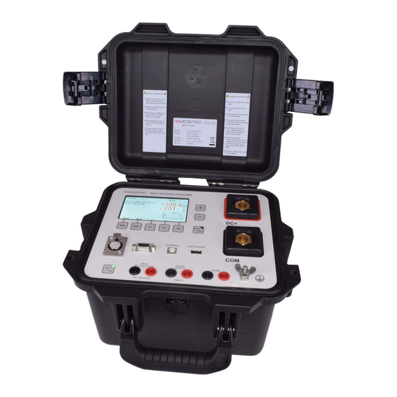
- Page 1 Portable Micro-Ohmmeter VG-BAT-x00 OPERATING MANUAL...
- Page 2 Operating manual VG-BAT Warranty Mostec warrants this product to be free of manufacturing defects for a 2-year period after the original date of purchase. Within this period, defective products will be repaired free of charge provided that the defect occurred during normal operation. This warranty does not cover damage to the product resulting from ordinary usage such as front panel scratches, broken control elements and corrosion, etc.
-
Page 3: Table Of Contents
Operating manual VG-BAT Index Page Safety Regulations ............................. 4 Battery care ..............................5 Battery disposal............................5 Operating Instructions ..........................5 Control Panel ............................. 6 Power ON ..............................7 Main Menu ..............................7 System Menu ............................. 8 System Menu, Description ......................... 9 10. -
Page 4: Safety Regulations
Operating manual VG-BAT 1. Safety Regulations Always comply with local safety regulations when using the Micro-Ohmmeter. Always connect protective earth (ground). Read and comply with the safety regulations in this manual before using Micro-Ohmmeter. Never open a breaker as long as the Micro-Ohmmeter is connected. High voltage/currents can occur at the input/output clamps. -
Page 5: Battery Care
This product contains lithium ion batteries and a coin cell. They are located inside the instrument. The Lithium ion coin cell can be safely removed by Mostec AG. 4. Operating Instructions 1. -
Page 6: Control Panel
Operating manual VG-BAT 5. Control Panel LCD 4.3" graphic display Keys to control the menu functions Increment/decrement keys for menus and values Start/Stop keys with status LED Remote control connector Accessories connector USB PC-Interface Data logger / USB stick Current clamp sense input Raw signal shunt voltage terminals Sense terminals DC - current output... -
Page 7: Power On
Operating manual VG-BAT 6. Power ON After power up the display shows the welcome message for 3 seconds. After that, the display shows the main menu. 7. Main Menu Iset = The previously set measuring current. The measuring current can be changed by using the [+] and [-] keys. -
Page 8: System Menu
Operating manual VG-BAT 8. System Menu Pressing [Ent] in the main menu leads to the system menu. In this menu, the user can navigate between the items using the [F1] and [F2] key. Pressing [F3] switches between the first and second page of the system menu. -
Page 9: System Menu, Description
Operating manual VG-BAT 9. System Menu, Description First Page Menu item Description Range of values SM 0 Measure mode(not available for battery types): single/continuous The measuring current flows continuously until it's interrupted by the user. Single = the measuring current only flows for a fixed given time. - Page 10 Operating manual VG-BAT Second Page Menu item Description Range of values SM 10 Time format: 12h/24h Switches between 24/12h formats SM 11 Date format: YYMMDD, DDMMYY, Switches between different date formats. MMDDYY SM 12 Time: 0…12 / 0…23 Adjusts the hour of the internal clock. SM 13 Time: 0…59...
- Page 11 Operating manual VG-BAT Submenu Measurement Analysis Enter this submenu by the [Ent] key in the system menu on item SM22. If the measurement analysis is switched on, then the resistance value will be compared with the selected limits. If the reading is within the selected limit the display shows “Reading: Pass”...
-
Page 12: Result Window
Operating manual VG-BAT 10. Result Window The result window can be activated by pressing the key [Esc] in the main menu. It will also be automatically activated if a measurement has been completed. The Micro-Ohmmeter stores the last 100 data sets. Unlimited data sets can be achieved by using an external USB stick. The window shows the time and date of the running test, storage location, ohmic value and test current. -
Page 13: Error Messages
Operating manual VG-BAT 13. Error Messages The Micro-Ohmmeter can detect and display different errors. Fault Cause Remedy Sense line broken Sense line defective or broken Verify the sense line connections Overflow Ohmic value too high for the Bad connection and/or too selected current large resistance Measuring current value not... -
Page 14: Application Example - One Side Grounded
Operating manual VG-BAT 15. Application Example - one side grounded Comply to the safety regulations and operation instructions when using the Micro- Ohmmeter. See page 4 and 5. Never use the instrument without the protective earth connections! Important: The sensing cables must be connected after the high current cables, as close to the test object as possible. -
Page 15: Application Example - Both Sides Grounded
Operating manual VG-BAT 16. Application Example - both sides grounded Comply to the safety regulations and operation instructions when using the Micro- Ohmmeter. See page 4 and 5. Never use the instrument without the protective earth connections! Important: The sensing cables must be connected after the high current cables, as close to the test object as possible. -
Page 16: Verify The Measuring Current
Operating manual VG-BAT 17. Verify the measuring current Comply to the safety regulations and operation instructions when using the Micro- Ohmmeter. See page 4 and 5. 1. Connect mV-Meter to the shunt output 2. Calculate the measuring current: Shunt voltage = 100uV/A Measuring mV Measuring Current = ------------------------------- Shunt voltage 100uV/A... -
Page 17: Technical Data
Operating manual VG-BAT 19. Technical Data Measuring ranges: 0...20.00µΩ, 0...200.0µΩ, 0...2.000mΩ, 0...20.00mΩ, 0...200.0mΩ 0...999.9mΩ Display: Sunlight readable LCD 4.3"graphic display with a resolution of 480x272 dots Display resolution: 0.01µΩ ... 0.1mΩ Accuracy: 0 ...1000µΩ, @ 200A / 25°C = ±0.05% FS 1 ... -
Page 18: Notes
Operating manual VG-BAT 20. Notes Page 18... - Page 19 Operating manual VG-BAT Page 19...
- Page 20 Operating manual VG-BAT 23.04.2018/V1.10 Page 20...
Need help?
Do you have a question about the VG-BAT Series and is the answer not in the manual?
Questions and answers