Advertisement
AB4G Audible Detector Base Installation Sheet
Description
This installation sheet applies to AB4G Audible Detector Base
units with model numbers GSA-AB4G and SIGA-AB4G.
The AB4G Audible Detector Base adds an audible output
function to any Signature Series detector. The output of this
detector base is field-configurable for output tone (steady or
temporal) and output volume (low or high dBA).
Depending on the system supporting the Signature loop, the
base can:
•
Follow the state of the device it supports
•
Be configured (in the SDU) for other operating modes
•
Be controlled by program rules
The base uses the same address and programming label as
the detector it supports.
Installation
Install this device in accordance with applicable national and
local codes, ordinances, and regulations.
Cautions
•
To avoid accidental damage to the panel, disconnect all
power before wiring the unit.
•
Do not loop the signaling circuit field wires around the
terminals.
Note:
Always connect the base to a continuous voltage,
whether the output tone on the audible detector base is set to
steady or temporal.
© 2014 UTC Fire & Security Americas Corporation, Inc.
Sleeping rooms:
In sleeping areas, use the high dBA output
and temporal tone settings.
AB4G-SB:
When using the AB4G-SB box, install a reinforcing
plate at every knockout. (Reinforcing plates are included with
the box.) Remove the knockout first and then slide the
reinforcing plate into the plastic housing. After the plate is in
place, install the conduit connector and nut. See Figure 1.
Typically, the base is configured to produce a high dBA
temporal tone and is connected to a notification appliance
circuit that outputs a continuous 24 VDC signal.
Refer to Figure 2 when following the installation steps given
below.
To install the audible detector base:
1.
The unit default is for high dBA output. To set the output to
low dBA, cut the circuit board trace as marked on the back
of the PC board. See Figure 3.
2.
The unit default is for temporal pattern output. To set the
output to steady tone, cut the circuit board trace as
marked on the back of the PC board. See Figure 3.
3.
Select and install a compatible electrical box, and then
bring the field wiring into the box.
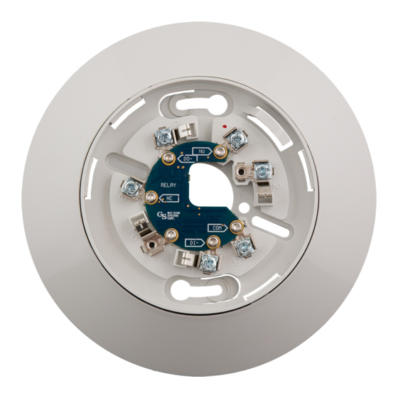
4.
Connect the field wiring to the terminals on the back of the
base plate. For the unit to function properly, observe
polarity. See Figure 3.
5.
Attach the base plate to the electrical box.
6.
Align the trim ring so that the four tabs on the ring mate
with the four slots in the base plate, and then press the
trim ring onto the base plate until the tabs lock.
7.
Attach the desired Signature detector to the base. Align
the arrows on the detector and trim ring, press the
detector into the base, and then rotate the detector until it
locks into place.
8.
Apply power and activate the unit to verify that it is
operating properly.
1 / 6
P/N 3100672-EN • REV 07 • ISS 23JAN14
Advertisement
Table of Contents

Subscribe to Our Youtube Channel
Related Manuals for Edwards AB4G


Summary of Contents for Edwards AB4G
- Page 1 The unit default is for high dBA output. To set the output to Description low dBA, cut the circuit board trace as marked on the back This installation sheet applies to AB4G Audible Detector Base of the PC board. See Figure 3. units with model numbers GSA-AB4G and SIGA-AB4G.
-
Page 2: Wiring Diagram
Wiring diagram Figure 1: Installing reinforcing plates on the AB4G-SB box Wire this device in accordance with applicable national and local codes, ordinances, and regulations. See Figure 3. For additional wiring details, see the applicable control panel installation manual. Figure 3: Output configuration and basic wiring Figure 2: Installing the Audible Detector Base AUX_RISER_IN ... -
Page 3: Specifications
Compatible detectors All Signature Series detectors [1] 90 (ref) 0 dBA Compatible electrical AB4G-SB surface box for audible base; boxes 4 in. square x 2-1/2 in. (64 mm) deep box; 75 and 105 −3 dBA 3-1/2 in. octagonal x 2-1/2 in. (64 mm) deep 65 and 110 −6 dBA... -
Page 4: Regulatory Information
This section describes applications typically found in the North Manufacturer Edwards, A Division of UTC Fire & Security American marketplace that apply to the AB4G and Signature Americas Corporation, Inc. audible bases. For additional examples, see the applicable 8985 Town Center Parkway, Bradenton, FL control panel application manual. - Page 5 Figure 4: Local alarm signaling application AB4G AB4G AUX_RISER AUX_RISER SLC SLC Figure 5: Zone alarm signaling application AB4G AB4G AUX_RISER AUX_RISER SLC SLC (1) Data from signature controller (2) Use a 24 VDC primary or auxiliary power supply that is UL/ULC Listed for fire protective signaling systems (3) Listed 24 V EOL supervising equipment P/N 3100672-EN •...
- Page 6 Figure 6: Synchronized alarm signaling application AB4G AB4G _RISER _RISER SLC SLC (1) Data from signature controller (2) Use a 24 VDC primary or auxiliary power supply that is UL/ULC Listed for fire protective signaling systems (3) Listed 24 V EOL supervising equipment 6 / 6 P/N 3100672-EN •...
Need help?
Do you have a question about the AB4G and is the answer not in the manual?
Questions and answers