Advertisement
Quick Links
Advertisement

Related Manuals for BobsCNC KL Series


Summary of Contents for BobsCNC KL Series
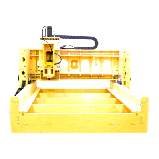
- Page 1 K L s e r i e s Table Assembly MANUAL Version 1.4...
- Page 2 Table of Contents Shop Safety: Precautions and Warnings ····················································· 3 Table Wood Components………………………………………………………………………….4 Leg Assembly…………………………………………………………………………………………...5 Frame Assembly……………………………………………………………………………………...6-10 Attaching the Legs…………………………………………………………………………………...11 Finished Picture……………………………………………………………………………………….12...
- Page 3 Look Safety Information and Hints. Indicates a serious risk of bodily harm, possible injury and death. This warning box is to be taken seriously. Any work must be carried out with extreme caution. Indicates a possible risk of injury that CAUTION can result from failure to follow this warning.
- Page 4 Table Wood Components Part # Description Photo Side Panel Lower Cross Support Upper Cross Support End Panel Side Leg Panel End Leg Panel Mid Brace Corner Brace 5/16 x 1 1/4 Machine Screws 5/16 Nut 5/16 Lock Nut...
- Page 5 Leg Assembly Align the tabs and slots of the Front, Back and Side Leg panels. Step 1 Secure with three 5/16 x 1 1/4 Machine Screws and Nuts per assembly. Repeat for all four leg assemblies.
- Page 6 Frame Assembly Step 1 Align the slots in the Upper and Lower Cross Supports as shown.
- Page 7 Align the tabs in the Lower Cross Support with the Slots in Side Step 2 Panel and secure with two 5/16 x 1 1/4 Machine Screws and Nuts. Repeat for other Side Panel.
- Page 8 Attach the four Corner Braces to the Side Panels using two 5/16 x 1 1/4 Step 3 Machine Screws and Nuts per corner as shown. NOTE: Make sure the slots in the Corner Braces (circled in red) face toward the End Panels...
- Page 9 Align the tab of the Lower Cross Support with the slot in the Mid Step 4 Brace and secure with two 5/16 x 1 1/4 Machine Screws and Nuts for each Mid Brace as shown.
- Page 10 Align the tabs and slots and attach the two End Panels using eight Step 5 5/16 x 1 1/4 Machine Screws and Nuts for each End Panel as shown.
- Page 11 Attaching the Legs NOTE: The Mounting Tab on the End Leg Panel fits through the slot in Step 1 the Corner Brace as shown. Slide the Mounting tab though the slot in the Corner Brace and attach the Leg Assembly to the End and Side Panel with eight 5/16 x 1 1/4 Machine Screws and Lock Nuts for each leg assembly.
- Page 12 Finished KL series Table...
Need help?
Do you have a question about the KL Series and is the answer not in the manual?
Questions and answers