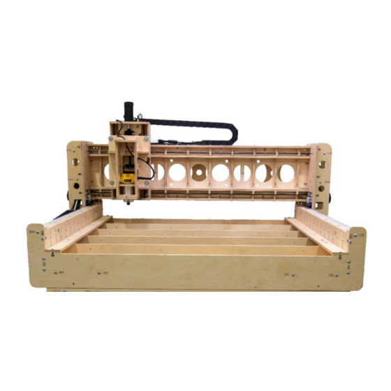
BobsCNC KL744 Assembly Manual
X frame assembly
Hide thumbs
Also See for KL744:
- Manual (67 pages) ,
- Assembly manual (39 pages) ,
- Getting started (9 pages)
Advertisement
Quick Links
Advertisement

Subscribe to Our Youtube Channel
Related Manuals for BobsCNC KL744


Summary of Contents for BobsCNC KL744
- Page 1 K L 7 4 4 X Frame Assembly MANUAL 4 of 8 Version 2.7 Page 1...
- Page 2 Table of Contents Safety First…………………………………………………………………………………………………...3 X Frame Assembly Parts Guide……….…………………………………………………………..4-5 X Frame Assembly Instructions ······································································ 6-20 Page 2...
- Page 3 Look Safety Information and Hints. Indicates a serious risk of bodily harm, possible injury and death. This warning box is to be taken seriously. Any work must be carried out with extreme caution. Indicates a possible risk of injury that CAUTION can result from failure to follow this Instruction.
- Page 4 X Frame Wood Components Part # Description Photo Frame Side Mid Rail Supports Rail Support Drag Chain Mount End Panels Side Brace Belt Rest Corner Brace Page 4...
- Page 5 X Hardware Components Part # Description Photo 5/16 x 1 1/4 Machine Screw 5/16 Nut 3/8” x 48” X Rail Page 5...
-
Page 6: Frame Assembly
X Frame Assembly Attach the ten X3 Rail Supports to the X1 Frame Side. Align the tabs of Step 1 the X3 Rail Supports to the slots of the X1 Frame Side, insert and secure with twenty 5/16 x 1 1/4 Screws and Nuts as shown NOTE: The Pocket holes on the X1 Frame Side must be placed face-down when attaching the X3 Rail Supports. - Page 7 NOTE: The finished X Frame Side Assemblies are designed to mirror each other as shown. You will be able to see how the slots, pocket holes, and access holes line up. Slots Pocket Holes Access Holes Page 7...
- Page 8 Step 2 Install two 10-24 Threaded Inserts into the X4 Drag Chain Mount as shown. 2 inserts Page 8...
- Page 9 Align the tabs of the X4 Drag Chain Mount with the slots in the X2 Step 3 Mid Rail Supports and secure with two 5/16 x 1 1/4 Machine Screws and Nuts. Inserts flanges on opposite side Page 9...
- Page 10 Step 4 third X2 Mid Rail beside it as shown. NOTE: In the photo below the assembly is setting on the KL744 Optional Table. Align slots of the X Frame Side Assembly with the X2 Mid Rail Supports as shown. Carefully slide the slots down until the bottom of the slot rests on the base of X Frame Side Assembly.
- Page 11 Left Side Assembled Right Side Assembled Page 11...
- Page 12 Insert the tabs of the X8 Corner Brace into the slots of the X Frame Step 5 Side Assembly as shown and secure with two 5/16 x 1 1/4 Machine Screws and Nuts. Repeat to install all four Corner Braces. Page 12...
- Page 13 Attach the X7 Belt Rest to the top of the X Frame Side Assembly. Step 6 Align the three slots of the X7 Belt Rest with the three tabs of the X Frame Side Assembly as shown and secure with seven 5/16 x 1 1/4 Machine Screws and Nuts.
- Page 14 Attach one of the X5 End Panels to the rear of the X Frame Step 7 Assembly. Align the slots of the X5 End Panel with the tabs at both ends of the X Frame Assembly and secure with twelve 5/16 x 1 1/4 Machine Screws and Nuts as shown.
- Page 15 Apply Teflon dry lube to the rail prior to installation. Hint Carefully slide an X Rail through the X3 Rail Supports until it is fits Step 8 into the pocket hold in the X5 End Panel as shown. NOTE: Do not snap the rod into place. NOTE: To make installing the rods easier you can slowly rotate the rail through the Rail...
- Page 16 With someone to assist you, carefully slide the Gantry Assembly Step 9 onto the X rails. Be sure the upper pulleys are riding on the upper rail and the lower pulleys are beneath the lower rail on both sides. Page 16...
- Page 17 Attach the remaining X5 End Panel to the front of the X Frame Step 10 Assembly. Align the slots of the X5 End Panel with the tabs at both ends of the X Frame Assembly and secure with twelve 5/16 x 1 1/4 Machine Screws and Nuts as shown.
- Page 18 On the Gantry Sides, using a 5/64 Allen Wrench, adjust the 8-32 Step 11 Set Screws to snug the lower pulley against the lower rail. Repeat for all four lower Set Screws. The pulley should be full engaged with the rail and only roll when the Gantry moves. NOTE: Remember to apply Locktite 243 to the threads of the Set Screws.
- Page 19 NOTE: The gap should be parallel as shown on both sides of the Gantry Assem- bly. Page 19...
- Page 20 Attach one of the X6 Side Braces to the X Frame Assembly and secure with Step 12 five 5/16 Machine Screws and Nuts as shown. Repeat for the other side. NOTE: For ease of installation set the 5/16 Nuts in the T-Slots before laying the X6 Side Brace in place.
Need help?
Do you have a question about the KL744 and is the answer not in the manual?
Questions and answers