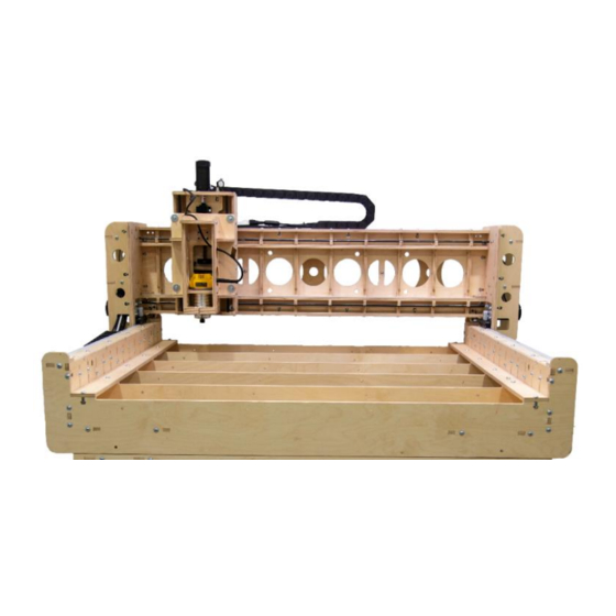
BobsCNC KL744 Assembly Manual
Gantry & bell-everman drive assembly manual
Hide thumbs
Also See for KL744:
- Manual (67 pages) ,
- Assembly manual (20 pages) ,
- Getting started (9 pages)

Subscribe to Our Youtube Channel
Related Manuals for BobsCNC KL744


Summary of Contents for BobsCNC KL744
- Page 1 K L 7 4 4 Gantry & Bell-Everman Drive Assembly Manual MANUAL 3 of 8 Version 2.8 Page 1...
-
Page 2: Table Of Contents
Table of Contents Safety First………………………………………………………………………………………………..3 Bell-Everman Drive Components……………………………………………………………….4 Bell-Everman Drive Assembly Instructions..……………………………………………….5-12 Gantry Wood Components………………………………………………………………………..13-14 Gantry Sides Assembly……………………………………………………………………………...15-22 Gantry Frame Assembly……………………………………………………………………………..23-29 Final Gantry Assembly………………………………………………………………………………..30-39 Page 2... -
Page 3: Safety First
Look Safety Information and Hints. Indicates a serious risk of bodily harm, possible injury and death. This warning box is to be taken seriously. Any work must be carried out with extreme caution. Indicates a possible risk of injury that CAUTION can result from failure to follow this instruction. -
Page 4: Bell-Everman Drive Components
Bell-Everman Drive Components Part # Description Photo BE 1 Bell-Everman Plate Idler Pulley Timing Pulley Servo Motor 10-24 Lock Nut 10-24 x 3/4 Socket Head Bolt 8 x 7 x 22 Bearing Allen Head M6 x 30 Shoulder Bolt Hardened Washers M6 Lock Nuts 3 mm Pulley Gauge Page 4... -
Page 5: Bell-Everman Drive Assembly Instructions
Bell-Everman Assembly Instructions CAUTION: The Bell-Everman Plate has been designed so that Shoulder Bolts must be press fit or carefully tapped into place with a hammer. Idler Pully sequence: Allen Head Shoulder Bolt/ Bearing/ four Hardened Washers / Idler Pulley/Bearing/ one Hardened Washer / Bell-Everman Plate / Lock Nut. - Page 6 Slide the M6 Shoulder Bolt, Bearing, and Hardened Step 2 Washers into the Idler Pulley as shown. Press the Assembled Components into the Idler Pulley Step 3 so that the Bearing is fully seated as shown. Page 6...
- Page 7 Slide the second Bearing onto the M6 Shoulder Bolt and Step 4 secure by pressing the Bearing into the Idler Pulley body as shown. Slide a Hardened Washer onto the M6 Shoulder Bolt. It Step 5 will serve as a spacer allowing the Idler Assembly to turn freely against the Bell-Everman Plate.
- Page 8 Step 6 Thread the M6 Shoulder Bolt through the mounting holes in the Bell-Everman Plate. Gently tap the head of the Bolt, if necessary, for fit. Make sure the Hardened Washer is in place before securing the M6 Lock Nut as shown. Tighten with Allen wrench and socket.
- Page 9 Step 7 Repeat Steps 1 thru 6 attaching the remaining 3 Idler Assemblies to the Bell-Everman Plates as shown. Page 9...
- Page 10 Attach the Timing Pulley to the X1, X2 and Y Servo Step 8 Motor Shafts Remove the two set screws from the Timing Pully. Step 9 Apply Lock-Tite to the threads and reinstall. Slide the pulley onto the Servo Motor Shaft. Using Step 10 the enclosed 33 mm Belt Pulley Gauge, properly position the pulley.
- Page 11 Slide the Servo Motor shaft with attached Timing Step 11 Pulley through the Bell Everman Plate and secure with four 10-24 x 3/4” Socket Head Bolts and four Lock Nuts as shown. These four bolts will be tightened in a later step. Finished plate from the front Page 11...
- Page 12 NOTE the orientation of the Servo and Controller Wires in relation to the front of the Bell Everman Plate assembly. The wires for the Servo Motor on the Y axis must be routed to the right side as shown. The X1 and X2 axes are routed toward the top.
-
Page 13: Gantry Wood Components
Gantry Wood Components Part # Description Photo Gantry Right Side Gantry Left Side Gantry Side Supports Gantry Side Support w/ wire bracket mount [left side only]. Adjustment Plate Cross Brace Top & Bottom Brackets [two per side] Drag Chain Mount Gantry Frame Page 13... - Page 14 Part # Description Photo Gantry Top and Bottom Support Gantry Back Brace Y Rail Support Horizontal Brace Box Brace X Home Switch Mount (6mm) Gantry Hardware Part # Description Photo SG25U bearings 5/16 Fender Washers 5/16 x 1 3/4 Hex Head Bolt 10-24 Insert 10-24 x 3/4Socket...
-
Page 15: Gantry Sides Assembly
Gantry Sides Assembly The tabs and slots have been engineered for a tight fit. Prior to assembly use a sanding block with 80 to 100 grit sandpaper to gently chamfer the edges of the tabs. Hint Step 1 Lay the G2 Gantry Left Side with the L designation facing down as shown. - Page 16 Step 2 Place the G4 Gantry Side Support as shown. Insert the tabs of the G8 Drag Chain Mount into the slots of the Side Support as shown. The G4 Side Support has two slots as shown. Page 16...
- Page 17 Insert the tabs of the Side Support Assembly into the slots Step 3 of the Gantry Left Side. Secure with six 5/16 x 1 1/4 Machine Screws and Nuts as shown. Page 17...
- Page 18 Insert the tabs of the G3 Gantry Side Support into the slots of Step 4 the Gantry Left Side as shown. Secure with five 5/16 x 1 1/4 Machine Screws and Nuts. Page 18...
- Page 19 Attach the G6 Cross Brace. Align the long slot of the Cross Step 5 Brace with the slots in the Side Supports and the Gantry Left Side as shown. Secure with three 5/16 x 1 1/4 Machine Screws and Nuts. Page 19...
- Page 20 Attach the G7 Top Bracket. Align the Top Bracket with the Step 6 slots in the Side Supports and the Gantry Left Side and slide into place as shown. Repeat with the G7 Bottom Bracket. Align the Bottom Bracket Step 7 with the slots in the Side Supports and the Gantry Left Side.
- Page 21 Secure the Top and Bottom Brackets with six 5/16 x 1 1/4 Step 8 Machine Screws and Nuts. Page 21...
- Page 22 Step 9 Repeat the process to assemble the mirrored Gantry Right Side Assembly as shown. Since the Right Side Assembly does not include a Drag Chain Mount the total number of Machine Screws and Nuts will be reduced by one . The number required for the Right Side is nineteen of each.
-
Page 23: Gantry Frame Assembly
Gantry Frame Assembly Align the tabs of the G12 Y Rail Support with slots Step 1 on the G9 Gantry Frame. Insert and secure with three 5/16 x 1 1/4 Machine Screws and Nuts as shown. Page 23... - Page 24 Repeat the process to install all ten G12 Y Rail Supports as Step 2 shown. Assembled Top View Assembled End View Page 24...
- Page 25 Align the tabs and slots of the G13 Horizontal Brace with Step 3 the slots of the Gantry Frame Assembly and tap in place. Secure with six 5/16 x 1 1/4 Machine Screws and Nuts as shown. Repeat the process to attach the second G13 Horizontal Brace as shown. Page 25...
- Page 26 Lay the G10 Gantry Bottom Support on the work surface. Step 4 Align the tabs and slots of the Frame Assembly with the slots of the G10 Gantry Bottom Support. Tap in place and secure with fourteen 5/16 x 1 1/4 Machine Screws and Nuts.
- Page 27 Insert the G11 Gantry Back Braces and secure in place Step 5 with six 5/16 x 1 1/4 Machine Screws and Nuts as shown. Attach the G10 Gantry Top Support and secure in place Step 6 with twenty 5/16 x 1 1/4 Machine Screws and Nuts as shown.
- Page 28 Slide the G14 Box Brace as Step 7 shown and secure with three 5/16 x 1 1/4 Machine Screws and Nuts as shown. Repeat for the second G14 Box Brace as shown. Apply Teflon dry lube to the rail prior to installation. Hint Carefully insert the Y Rail into the Y Rail supports and Step 8...
- Page 29 The Y Rail should be roughly centered on the Gantry Frame Step 9 Assembly as shown. Repeat to install the bottom Y Rail as shown. Page 29...
-
Page 30: Final Gantry Assembly
Final Gantry Assembly Align the tabs of the Left Gantry Side Assembly making Step 1 sure the pocket holes are aligned to receive the Y Rail Ends as shown. Secure with eight 5/16 x 1 1/4 Machine Screws and Nuts. Pocket Holes that receive the Y Rail Ends. - Page 31 Step 2 Repeat to attach the Right Gantry Side assembly. Page 31...
- Page 32 NOTE: Find the two holes in the underside of the G10 Step 3 Gantry Top Support. They will be behind the center G11 Gantry Back Brace as shown. Insert the two 10-24 threaded inserts with an Allen wrench as shown. These inserts will help attach the Gantry Drag Chain in a later step.
- Page 33 Insert the two 10-24 Threaded Inserts on the bottom Step 4 side of the Drag Chain Mount and tighten in place with an Allen wrench as shown. NOTE: The G8 Drag Chain Mount is located on the left side of the Gantry Side Assembly. Holes for threaded inserts.
- Page 34 Insert a 10-24 Threaded Insert in each corner. Screw the Step 5 Insert in the hole furthest from the Gantry Side Assembly. Tighten in place with an Allen wrench as shown. Page 34...
- Page 35 Slide both G15 X Home Switch Mounts into the slot at Step 6 each end on the underside of the Gantry Bottom Assembly. Secure each in place with one 10-24 x 3/4 Socket Head Bolt. X Home Switch Mount Locations. Page 35...
- Page 36 NOTE: Set the Gantry on the work surface resting on the Top Plate with the bottom of the Gantry Side facing up. Insert the 8 x 32 Set Screw into each of the factory Step 7 installed Threaded Inserts in the bottom of both sides of the Gantry Side Assemblies as shown.
- Page 37 Install four SG25U Bearings on both Gantry Sides as Step 8 shown. Tighten the Bearings in the round holes but only snug the Bearings mounted in the elongated holes. These will be fully tightened in a later step. Bearing sequence: Hex-head / Bearing/ Fender Washer / Plywood / Fender Washer / Locknut.
- Page 38 Insert four 5/16 Lock Nuts into the Left Gantry Side Step 9 Assembly as shown. Insert 5/ 16 Lock Nuts Page 38...
- Page 39 Position the G5 adjustment plate as shown Step 10 Place four Fender Washers and insert four 5/16 x 1 1/4 Machines screws through the Lock Nuts and snug, allowing the G5 Adjustment Plate to slide freely. Snug the Screws and washers so that the G5 Adjustment Plate slides freely.
Need help?
Do you have a question about the KL744 and is the answer not in the manual?
Questions and answers