Table of Contents
Advertisement
Advertisement
Table of Contents

Related Manuals for Inventis TRUMPET


Summary of Contents for Inventis TRUMPET
- Page 1 TRUMPET EAL EAR MEASUREMENTS SYSTEM UDIOMETER ANUAL...
- Page 3 Internal inspection and servicing of the instrument must be entrusted entirely to technicians approved by Inventis S.r.l. Copyright: Inventis S.r.l. is the owner of the copyright on this manual. It is forbidden to copy, reproduce or alter the manual, in its entirety or in part, without the express written authorization of Inventis S.r.l..
-
Page 5: Table Of Contents
Summary Summary ..................v CHAPTER 1 Safety: warnings and information ....1 User Manual ............1 Operator responsibilities ........1 Intended use of the device ........2 Indication for use and end users of the device..2 Precautions .............. 3 Disposal ..............6 Conformity ............... - Page 6 Replaceable parts ..........41 Repairs and technical assistance ......42 Enable new licenses ..........42 Firmware upgrade ..........43 Calibration of microphones by code....43 APPENDIX A: Technical Specifications ......45 REM specifications ..............45 Audiometer specifications ............47 Other specifications ..............53 APPENDIX B: Specifications of speaker for free field tests ....................
-
Page 7: Chapter 1 Safety: Warnings And Information
Be sure to read this manual through completely, so that all of the features offered by the Trumpet instrument can be used to their full potential. In particular, be sure to read this chapter in its entirety, as it contains information and warnings that are of fundamental importance in ensuring safe and correct use of the device. -
Page 8: Intended Use Of The Device
Trumpet can be also an audiometer. An audiometer is a device that helps the operator in defining the patient’s auditory sensitivity by generating and delivering to the patient sound stimuli of different types and intensities for diagnostic purposes. -
Page 9: Precautions
Use only the power adapter supplied by Inventis s.r.l. The Trumpet is a medical device: if connected to a computer (or any external device) located within the "patient area" (as defined in EN 60601-1-1), this likewise must be a medical... - Page 10 (as habitually occurs in soundproof booth installations). If the transducers are not connected directly to the Trumpet , a new calibration procedure will be required before the instrument is used.
- Page 11 1.4.4 Avoiding discomfort for the patient The Trumpet is capable of generating pure tones at an intensity potentially harmful to the patient (up to 90-100 dB SPL). Take particular care over the intensity of the tone before presenting it: studies have shown that exposure...
-
Page 12: Disposal
ISPOSAL Like any other electronic device, the Trumpet contains certain extremely hazardous substances such as cadmium or mercury, albeit in extremely small proportions. If released into the normal refuse collection system without suitable preliminary treatment, these substances can cause serious damage to the environment and to health. -
Page 13: Conformity
ONFORMITY The Inventis Trumpet device is a class II device, in accordance with Annex IX of the medical devices directive 93/42/EEC as amended and supplemented by directive 2007/47/EC. - Page 14 instructions, may cause harmful interference to radio communications. However, there is no guarantee that interference will not occur in a particular installation. If this equipment does cause harmful interference to radio or television reception, which can be determined by turning the equipment off and on, the user is encouraged to try to correct the interference by one or more of the following measures: •...
-
Page 15: Symbols On Labels
In particular, the number comprises these segments: first 5 characters: Inventis product code characters 6 and 7: year of manufacture ("16" denotes 2016) character 8: model series characters 9-13: pro serial number... -
Page 17: Chapter 2 Introduction
The Trumpet is also a diagnostic audiometer that can be used to perform pure tone and speech audiometry by air or bone conduction. - Page 18 QuickSIN Ch. 2 AC, FF If the power adapter of the Trumpet is disconnected during an audiometry exam, only AC (Air Conduction) and BC (Bone Conduction) modes remain enabled, whereas FF (Free Field) mode is disabled. To enable free field mode, the power adapter must be reconnected (see Chapter 3 Installation).
-
Page 19: Accessories
CCESSORIES The Trumpet can be supplied with all or only certain of the accessories described, depending on the module purchased. If a licence is purchased at a later time, then the corresponding accessories will also be supplied (those not included in the version of the instrument purchased initially). - Page 20 • Clip-on talk-back microphone • Inventis Software Suite • USB cable • Medical grade power adapter 15V/2A • Operator Manuals Compatibility has been verified only with transducers and accessories supplied by Inventis S.r.l. Do not use other transducers or accessories.
- Page 21 Insertion of probe tube The Trumpet comes with a set of probe tubes (REM licence). To insert this accessory, position the blue part of the tube over the metal cylinder that provides the housing for the tube (A in the illustration) and push in gently until fully home.
- Page 22 The status LED will begin to blink in blue while searching for the Trumpet, and it will become orange when it is connected to it. If the Trumpet is not found (it is necessary that the device is connected to the power supply and to a switched-on PC via USB), the probes will continue to blink in blue and will turn off after some minutes.
- Page 23 If the probes are sold together with the Trumpet they will already be paired with the device, otherwise before using them it is necessary to perform the...
- Page 24 In case of any problemi it is possible to turn off the probes manually by keeping the button pressed for more than 10 seconds. They are however turned off every time that Trumpet is not in use by Maestro, unless they are in charge position.
-
Page 25: Preparation For An Rem Test
2.2.4 Probe tube calibration (REM) The position for calibration of the probe microphones is indicated below (refer to Maestro – Fitting and hearing aid test functionalities – User Manual for further information on how to proceed with calibration). The tip of the probe tube must be inserted into the relative guides, as near as possible to the reference microphone, and the headset placed at around 1 metre from and in front of the active speaker. - Page 26 2.3.1 Measurements in the ear When preparing the patient for an REM test, observe the following procedure: Position the patient at around 1 metre from and facing the speaker of the instrument, and in such a way that the ears are placed approximately at the same height as the instrument.
- Page 27 in the relative hole (if necessary, refer to heading 2.2.1 Probes (REM) for further information) and position the tube as illustrated below: In this way it will be possible to ensure the probe tube is kept straight when inserted into the auditory canal. If required for the measurement (i.e.
- Page 28 Should it be impossible to rely on the cooperation of the patient for the entire duration of an REM test, measurements can be acquired by way of a coupler using the RECD unit, or a Drum instrument connected to the same PC as the Trumpet.
- Page 29 RECD unit Before proceeding with the test, the speaker of the RECD unit must be equalized and the microphones calibrated. The operation requires that the coupler microphone and the reference microphone, suitably aligned one with another, should be positioned on the speaker of the RECD unit as illustrated in the image below.
- Page 30 Adapter (1) is designed for use with ITE, ITC and CIC hearing aids. Make certain that hearing aid is securely connected by using adhesive insulating putty. Adapter (2) allows connection of BTE type hearing aids to coupler using an ear hook. Adapter (3) is designed for use with RIC hearing aids.
- Page 31 Before a fitting procedure can be carried out using the RECD unit, the operator must always begin with the acquisition of an RECD curve, so that all the measurements made with the coupler can effectively simulate those normally obtainable in the ear. The software will enable the coupler measurement functionality only after the acquisition of an RECD curve has occurred.
- Page 32 Once the measurement in the ear has been obtained, the response in the coupler can be measured. Electing to use a disposable tip for acquisition of the measurement in the ear, the response in the coupler can be measured only with the adapter (1): this situation is identified as the HA1 configuration.
- Page 33 The response in the auditory canal can also be measured using the earmold of the patient's hearing aid, rather than a disposable tip. Likewise in this instance, the probe tube must first be inserted in the auditory canal of the patient as described in Heading 2.3.1, following which the mold, connected previously to the insert transducer, can be placed in the ear.
- Page 34 HA1-mold configuration The second configuration, on the other hand, identified as HA2, requires the connection of the adapter (2) to the coupler. In this instance, the only action required is to connect the outlet of the adapter (2) to the insert transducer using the 25 mm silicone tube, as shown in the following figure: HA2-mold configuration...
- Page 35 The only action required is to connect the Drum to the same PC as the Trumpet. For an overview of how the hearing aid is positioned correctly in the Drum instrument, refer to the Heading Position the hearing aid in the test chamber of the relative manual: Drum –...
-
Page 37: Chapter 3 Installation
CHAPTER 3 Installation Whilst the installation of the Trumpet device is a relatively simple procedure, it should be entrusted to a person with the requisite skills. If the installation is not performed correctly, the system could be affected by safety problems when in use. - Page 38 Plug the transducers and accessories into the respective sockets as indicated in the following table: Connector Accessory PAT. RESP Patient response button Bone vibrator Supra-aural headphones (TDH-39 or DD45) for Air AC L and AC R Conduction: right (AC R) and left (AC L) TALK BACK Microphone used by patient Microphone used by operator to communicate with...
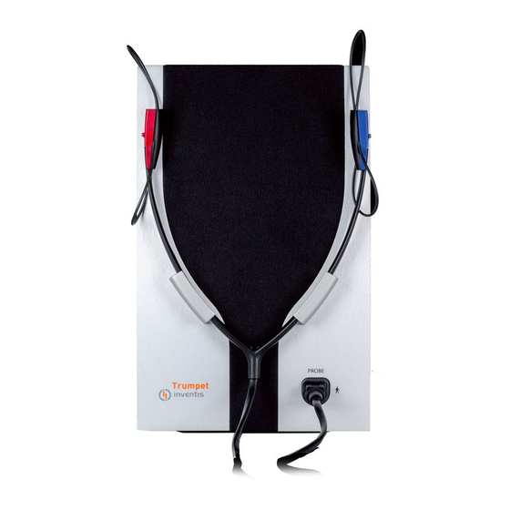
- Page 39 100 V and 240 V, with frequency between 50 Hz and 60 3.1.2 Front Panel A socket located at the bottom right hand corner of the Trumpet (the only connector on the front panel) is used to plug in the wired probes used for...
- Page 40 Set of wired probes used for REM measurements A Led positioned around the connector indicates the communication status between the Trumpet and the computer. Whenever the device is communicating with the PC controlling it, the Led will remain alight. NOTE: To conduct an REM test, the operator must connect only the USB cable and the power adapter to the rear panel —...
- Page 41 3.1.3 Connection diagrams for REM mode Wired REM probes Communication with patient RECD measurements...
- Page 42 PC/Power supply 3.1.4 Connection diagrams for audiometry mode AC/BC transducers...
- Page 43 Speakers for free field tests Option 1: External speakers Option 2: RECD speaker + built-in Trumpet speaker (*) Option 3: Built-in Trumpet speaker only (*) In this configuration, the built-in speaker functions as the left hand and the RECD speaker as the right hand.
- Page 44 AUD transducers (optional) When securing the Trumpet to a VESA wall mount, take care to use M4 screws that penetrate the threaded holes to a depth of no more than 6 mm.
-
Page 45: Chapter 4 Maintenance
Transducers are manufactured utilizing ultra-fragile diaphragms that could be damaged in the event of impact. Handle with care during maintenance operations. The Trumpet device do not require any special periodic maintenance other than calibration and normal cleaning, both of which are described in this chapter. -
Page 46: Periodic Checks
Check communication with the patient. LEANING AND MAINTENANCE OF TRANSDUCERS Do not use liquids or sprays to clean the Trumpet. When cleaning the device, use a soft cloth moistened with a mild detergent. The headphone cushions and the bone vibrator are made of biocompatible... -
Page 47: Replaceable Parts
The probe tubes are disposable, and accordingly, must not be washed and reused but changed for each new patient. No part of the Trumpet or of the relative accessories is suitable for sterilization in an autoclave, or for other thermal sterilization or disinfection procedures. -
Page 48: Repairs And Technical Assistance
Tool” software can be requested from the Inventis Service department. On receiving the zip file, extract and run the RE1LicensesActivationTool.exe. Be sure to have the license key available. Connect the Trumpet to the PC with the USB cable provided and plug the adapter into the mains power socket (for more information, consult the chapter 3 of the Trumpet User Manual). -
Page 49: Firmware Upgrade
The licenses currently active on the device are shown in the central area of the window. Enter the license key received from Inventis in the 5 fields (4 characters per field), exactly as written on the license document. Now click the “Enable License”... -
Page 51: Appendix A: Technical Specifications
APPENDIX A: Technical Specifications REM specifications REM classification Real Ear Measurement system, class 2a (MDD 93/42) REM GENERAL SPECIFICATIONS 125 Hz – 12 kHz Frequency range Reference microphones 40 – 110 dB SPL measurement range Probe microphones 40 – 130 dB SPL measurement range 50 dB SPL –... - Page 52 • Pink noise (PN) • White noise (WN). REM MEASUREMENTS AVAILABLE • REUR / REUG (single side and bilateral) • REOR / REOG (single side and bilateral) • REAR / REAG / REIG (single side and bilateral*) RECD • MPO (single side and bilateral*) •...
-
Page 53: Audiometer Specifications
Audiometer specifications Audiometer classification Pure tone audiometer type 2 and speech audiometer class A (IEC 60645-1, ANSI S3.6) SIGNALS AVAILABLE FOR AUDIOMETRY Type • Tone • Warble tone • MIC input for speech audiometry (live speech)* • Narrow band noise (NBN) •... - Page 54 • Stenger PURE TONES AND WARBLE AVAILABLE FREQUENCIES AND MAXIMUM OUTPUTS Freq. TDH39 ER-3C Int. Ext. (Hz) DD45 (dB HL) (dB HL) (dB HL) (dB HL) (dB HL) 1.000 1.500 2.000 3.000 4.000 6.000 8.000 SPEECH AUDIOMETRY MAXIMUM OUTPUTS TDH-39 DD45 ER-3C Int.
- Page 55 NBN, WN AND SN MASKING AVAILABLE FREQUENCIES AND MAXIMUM OUTPUTS Freq. TDH39 DD45 ER-3C Int. Ext. (Hz) (dB FL) (dB EM) (dB EM) (dB EM) (dB HL) (dB HL) 1.000 1.500 2.000 3.000 4.000 6.000 8.000 dB EM dB EM dB EM dB EM dB HL...
- Page 56 COMPATIBLE TRANSDUCERS Type Manufacturer Model Impedance Supra-aural Telephonics Corp. TDH39 10 ohm (1 kHz) headphones Supra-aural Radioear Corp. DD45 10 ohm (1 kHz) headphones Insert earphones Etymotic Research Inc. ER-3C 10 ohm (1 kHz) Bone vibrator Radioear Corp. 10 ohm (1 kHz) AMBIENT NOISE ATTENUATION VALUES FOR TRANSDUCER TDH 39 / DD45...
- Page 58 SPEECH AUDIOMETRY REFERENCE EQUIVALENT THRESHOLD VALUES IEC 60645-1 TDH39 DD45 ER 3C Free field Referred to 0 Coupler: ANSI S3.7 (NBS-9A) / IEC IEC 60318-5 IEC 60318-6 degrees 60318-3 (6cc) incidence [re 20 µPa] [re 20 µPa] [re 20 µPa] [re 1 µN] [re 20 µPa] 20.0...
-
Page 59: Other Specifications
Other specifications CONTROL OF DEVICE • By way of Inventis Maestro software installed on PC. POWER SUPPLY Consumption 30 Watts 15V, 2A d.c. utilizing external adapter rated 100- Power supply 240 Vac 50/60 Hz (included in the pack), responding to EN 60601-1 standard... - Page 60 AMBIENT CONDITIONS Temperature between +15°C and +35°C Relative humidity: between 30% and 90% (no Operation condensation) Pressure: between 700 hPa and 1060 hPa Temperature between -10°C and +50°C Transport and storage Relative humidity: 90% max, no condensation Pressure: between 500 hPa and 1060 hPa Warm-up time 1 minute MECHANICAL...
- Page 61 HEARING SAFETY FEATURES Alert situations: audible signal levels higher than 100 dB HL (IEC 60645-1) Safety measures: Audiometer Activation of “higher dB” button required to raise intensity beyond 100 dB HL Warning on test screen Activation of channel "Norm. ON" function inhibited Alert situations: audible signal levels above UCL thresholds, or above a customized value between 110 and 130 dB SPL, registering in the auditory canal...
- Page 62 SPECIFICATIONS OF OUTPUT TRANSDUCERS Output Voltage available Nominal impedance 10 Ω TDH 39 16Vpp 10 Ω DD45 16Vpp 10 Ω ER 3C / RECD 16Vpp 10 Ω B 71 16Vpp 4-8 Ω Free field (SPKF), 16Vpp 1Vrms with 32 Ω load Monitor SPECIFICATIONS OF SIGNALS AVAILABLE Pure random noise, filtered...
- Page 63 D-80339 Műnchen Notified body number 0123 Inventis will make available on request circuit diagrams, component part lists, descriptions, calibration instructions or other information that will help service personnel to repair those parts of the device that are designed by Inventis as repairable by service personnel.
-
Page 65: Appendix B: Specifications Of Speaker For Free Field Tests
APPENDIX B: Specifications of speaker for free field tests To produce the intensity levels in free field conditions specified in Appendix A, the speaker utilized must meet the specifications indicated below. Speaker specifications: Minimum input power 25 W Ω Nominal impedance Sensitivity (at 1 m for 1 W, 1 kHz) 93 dB SPL >... -
Page 67: Appendix C: Troubleshooting
Transducer not Connect the transducer to the connected to correct correct output output No signal from a transducer Contact Inventis service Transducer damaged department or dealer Connect the patient response Wrong connection No signal from button to the correct socket... - Page 68 Adjust the TALK BACK TALKBACK volume too volume by way of the Maestro control USB port of the Connect the instrument to a computer not working different USB port Connection between PC and device cannot be Replace the USB cable established USB cable damaged (standard USB cable, type...
- Page 69 0.5 m REM probes or reference If the problem persists after microphone not several attempts, contact functioning properly customer service Contact the Inventis technical service department A test cannot be Optional test not to obtain the license, accessed activated...
- Page 70 Speaker faulty Contact customer service When using the instrument in conjunction with a soundproof booth, check that the connections both inside the booth and between the booth and the instrument are correct and secure.
-
Page 71: Appendix D: Electromagnetic Emissions
At all events, there can be no guarantee that interference will not occur in certain situations. The Trumpet must not be used in close proximity to other equipment or stacked together with other equipment. If this cannot be avoided,... - Page 72 Manufacturer's indications and declaration - electromagnetic emissions The Trumpet is designed for use in an electromagnetic environment as specified below. The user of the Trumpet must ensure that the instrument is operated in ambient conditions as specified. Electromagnetic environment -...
- Page 73 Manufacturer's indications and declaration - electromagnetic immunity The Trumpet is designed for use in an electromagnetic environment as specified below. The user of the Trumpet must ensure that the instrument is operated in ambient conditions as specified. Electromagnetic Test level to EN...
- Page 74 RF transmitters, it may be necessary to conduct an electromagnetic survey on site. If the field strength measured at the point where the Trumpet is in use exceeds the applicable RF level of compliance indicated above, check the operation of the instrument closely, to ensure that its performance levels meet the required standards.
- Page 75 The Trumpet is designed for use in electromagnetic environments where radiated RF interference phenomena are kept under control. The user of the Trumpet can help to prevent electromagnetic interference by ensuring that a minimum recommended...
Need help?
Do you have a question about the TRUMPET and is the answer not in the manual?
Questions and answers
How does Trumpet work with GN software? E.g Beltone Solus MAx