Table of Contents
Advertisement
Quick Links
Instruction Manual
Direct Operated and High Response Type
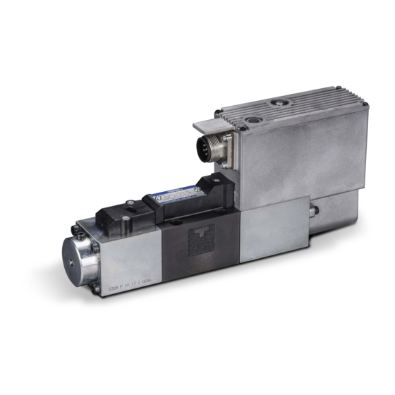
Proportional Electro-Hydraulic
Directional and Flow Control Valves
Model: ELDFG-01EH-*-*-*-*-*-10
Model: ELDFG-03EH-*-*-*-*-*-10
- To ensure safe and correct use of the product -
● To ensure proper handling of the product, read this manual thoroughly before use.
● Be sure to follow the instructions described in the Safety Precautions section of this manual.
● Keep this manual at hand for future reference.
● When creating instruction manuals for systems equipped with the product, be sure to reflect
the contents of this manual in such documents.
ELDFG-*EH Series
YUKEN KOGYO CO., LTD.
Doc. No.
Pub. EM-1359
Date of Issue
December 20, 2013
Public Relations Group,
Products Publicity Section,
Sales Administration Department
Advertisement
Table of Contents

Subscribe to Our Youtube Channel
Summary of Contents for YUKEN KOGYO ELDFG-01EH 10 Series
- Page 1 ● Be sure to follow the instructions described in the Safety Precautions section of this manual. ● Keep this manual at hand for future reference. ● When creating instruction manuals for systems equipped with the product, be sure to reflect the contents of this manual in such documents. YUKEN KOGYO CO., LTD.
- Page 2 EM-1359 About This Manual ● Some figures and illustrations in this manual are simplified and may not be an exact representation of the product. ● The contents of this manual are subject to change without prior notice as improvements are made to the product.
- Page 3 Regardless of their classification, all safety precautions contain important instructions. Be sure to follow them. YUKEN KOGYO CO., LTD. assumes no liability for any accident or damage arising from the use or operation of the product in a manner other than specified in this manual.
- Page 4 EM-1359 Always follow the safety precautions. DANGER Never use the product in an explosive Foreign matter in hydraulic fluid may result atmosphere where flammable gases or in malfunction of the product. Keep explosives are handled. Doing so may hydraulic fluid clean (NAS 1638 class 10 or result in a fatal accident, such as fire or better).
-
Page 5: Table Of Contents
EM-1359 Table of Contents 1. Introduction 1.1 Intended users of the product························································· 5 1.2 Intended purpose ··········································································· 5 1.3 Product check ················································································ 5 2. About the product 2.1 Model number designation ····························································· 6 2.2 Specifications ················································································· 6 - 7 2.3 External dimensions/valve mounting surface dimensions ·············· 8 - 9 2.4 Fail-safe function ············································································... -
Page 6: Introduction
The product should be handled by users with basic knowledge of hydraulics and electrics (who are at least equivalent to a class-2 hydraulic system control engineer, who have received technical training from YUKEN KOGYO, or who can fully understand the contents of this manual) or under the supervision of such personnel. -
Page 7: About The Product
EM-1359 2. About the product 2.1 Model number designation ELDF - 01 - 35 - 3C2P - XY Rated Flow Series Type of Valve Amplifier Direction Fail-Safe Input Signal/Spool Design L/min Spool Type * Number Mounting Size Type of Flow Function Travel Monitoring Number... - Page 8 EM-1359 2.2.1 Range of flow control ● Control Method: 4-Way Valve Valve Pres. Diff. [MPa] Valve Pres. Diff. [MPa] ● Control Method: 3-Way Valve Valve Pres. Diff. [MPa] Valve Pres. Diff. [MPa] - 7 -...
-
Page 9: External Dimensions/Valve Mounting Surface Dimensions
EM-1359 2.3 External dimensions/valve mounting surface dimensions ELDFG-01EH-*-*-XY-*-*-10 Indicator Lamp Cylinder Port “A” Tank Port “T“ Cylinder Port “B“ Air Vent 3 Hex. Soc. Color Indicator Lamp Green Power Supply Deviation Alarm Protective Screw for NULL Adjuster Hole Pressure Port “P” 5.5 Dia. - Page 10 EM-1359 ELDFG-03EH-*-*-XY-*-*-10 Indicator Lamp Cylinder Port “A” Pressure Port “P“ Cylinder Port “B“ Air Vent 3 Hex. Soc. Color Indicator Lamp Green Power Supply Deviation Alarm ● Protective Screw for NULL Adjuster Hole 7 Dia. Through M5 (+) Thd. Tank Port “T ”...
-
Page 11: Fail-Safe Function
EM-1359 2.4 Fail-safe function With reference to the information given below, select the option for the fail-safe function according to the use of applications. A separate safety circuit should be provided if the hydraulic actuator must be reliably held or stopped to ensure safety in the event of electric failure (power failure, power cable disconnection, etc.) or upon startup. -
Page 12: Valve Installation
EM-1359 3. Valve installation 3.1 Valve mounting surface dimensions For the valve mounting surface, see the table below. For the detailed dimensions of the mounting surface, see 2.3 or the installation drawing. The mounting surface should have a good machined finish, e.g. surface roughness of 6-S. Valve Model Number Mounting Surface ELDFG-01EH... -
Page 13: Installation
EM-1359 3.5 Installation Upon valve installation, check the port locations with reference to the installation drawing. Be careful to install the valve in the correct direction for the proper operation of equipment. When mounting the valve, use four hexagon socket head cap bolts supplied with the product. Tighten the bolts gradually and evenly in the order shown by the numbers 1 to 4 below and repeat this cycle two to three times. -
Page 14: Wiring
EM-1359 4. Wiring To drive the valve, it must be wired to the power supply and the setting adjuster. Connect the cable/connector to the connector port of the valve as shown below. Connector Port of the Valve Connector (To Be Separately Prepared) Cable Cable Connection for the Valve According to the input signal type, determine the cable length with reference to the table below. -
Page 15: Connection Between The Cable And The Connector
EM-1359 4.2 Connection between the cable and the connector The connector is not included with the valve. Prepare a connector that conforms to the standard specified by YUKEN and wire it correctly by following the instructions for the connector. Connect the connector to the power supply and the setting adjuster via the recommended cable with reference to the connector pin assignment shown in 2.5 or the installation drawing. -
Page 16: On-Board Amplifier
EM-1359 5. On-board amplifier 5.1 Appearance of the on-board amplifier NULL Adjuster This trimmer is used to adjust the neutral position of the valve spool. It is set by default. If neutral position adjustment is required for the load conditions, remove the protective screw (M5) and turn the trimmer behind the screw. -
Page 17: Block Diagram
EM-1359 WARNING ♦ When installing/relocating the valve or connecting the cable, be sure to turn off the main power supply in advance. Failure to do so may cause electric shock, fire, amplifier malfunction, or failure. ♦ Be sure to use the specified power supply voltage (24 V DC). Failure to do so may cause fire or electric shock. -
Page 18: Description Of Signals
EM-1359 5.4 Description of signals 5.4.1 Input signal and spool travel monitoring Input signals to drive the valve are used for spool position control. The types of input and spool travel monitoring signals differ depending on the model number. Model Number Input Signal Spool Travel Monitoring ELDFG-*EH-*-D... -
Page 19: Operating The Valve
EM-1359 6. Operating the valve 6.1 Adjustment ● The neutral position of the valve spool has been adjusted. Do not disassemble the valve to adjust the neutral position. ● All trimmers for the on-board amplifier are set by default. If the adjustment of the neutral position of the valve spool is required for the actual load conditions, perform NULL adjustment as described in 5.1. -
Page 20: Hydraulic Fluid
EM-1359 6.3 Hydraulic fluid 6.3.1 Fluid type Petroleum base oil: Use a fluid equivalent to ISO VG32 or 46. Synthetic fluid: Use a phosphate ester or polyol ester fluid. When phosphate ester fluids are used, prefix “F-” to the model number because the special seals (fluororubber) are required to be used. -
Page 21: Storage Of Unused Valves
10. Customer service If there are requests regarding our products or if any services are required, please contact the place of purchase, our customer support, or the following sales department. ● YUKEN KOGYO CO., LTD. International Sales Department, Global Business Division 4-4-34, Kamitsuchidana-Naka, Ayase, Kanagawa Pref.
Need help?
Do you have a question about the ELDFG-01EH 10 Series and is the answer not in the manual?
Questions and answers