Table of Contents
Advertisement
Quick Links
Advertisement
Table of Contents

Related Manuals for Data Translation DT9836 Series

Summary of Contents for Data Translation DT9836 Series
- Page 1 Title Page UM-21551-Z DT9836 Series User’s Manual...
- Page 2 Information furnished by Data Translation, Inc. is believed to be accurate and reliable; however, no responsibility is assumed by Data Translation, Inc. for its use; nor for any infringements of patents or other rights of third parties which may result from its use.
- Page 3 Changes or modifications to this equipment not expressly approved by Data Translation could void your authority to operate the equipment under Part 15 of the FCC Rules.
-
Page 5: Table Of Contents
Configuring the DT9836 Series Device Driver ........ - Page 6 Contents Period/Pulse Width Measurement ......... . 49 Edge-to-Edge Measurement .
- Page 7 Contents Output Triggers ............80 Output Clocks .
- Page 8 Contents Counter/Timers ............. 108 Tachometers.
- Page 9 Contents EP355 Screw Terminal Assignments ..........152 LED Status Indicators .
- Page 10 Contents...
-
Page 11: About This Manual
About this Manual The first part of this manual describes how to install and set up your DT9836 Series module and device driver, and verify that your module is working properly. The second part of this manual describes the features of the DT9836 Series modules, the capabilities of the DT9836 Series Device Driver, and how to program the DT9836 Series modules using the DT-Open Layers for .NET Class Library™... -
Page 12: Conventions Used In This Manual
• Items that you select or type are shown in bold. Related Information Refer to the following documents for more information on using the DT9836 Series modules: • Benefits of the Universal Serial Bus for Data Acquisition. This white paper describes why USB is an attractive alternative for data acquisition. -
Page 13: Where To Get Help
• Microsoft Windows Vista, Windows 7, or Windows 8 documentation. • USB web site (http://www.usb.org). Where To Get Help Should you run into problems installing or using a DT9836 Series module, the Data Translation Technical Support Department is available to provide technical assistance. Refer Chapter 7 for more information. - Page 14 About this Manual...
-
Page 15: Chapter 1: Overview
Overview DT9836 Hardware Features ........... . Supported Software . -
Page 16: Dt9836 Hardware Features
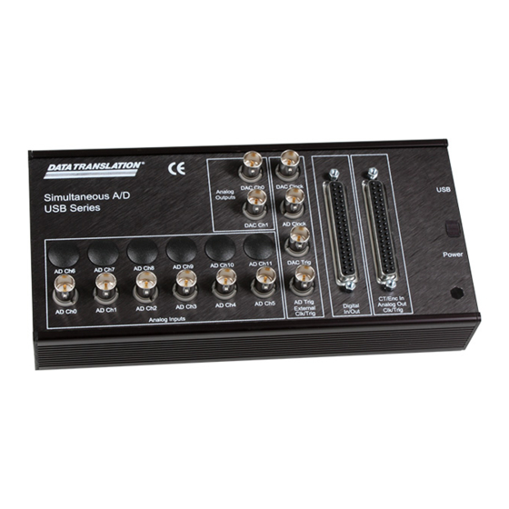
Chapter 1 DT9836 Hardware Features The DT9836 Series is a family of high-performance, multifunction data acquisition modules, shown in Figure 1, for the USB (Ver. 2.0 or Ver. 1.1) bus. Figure 1: DT9836 Series Module (BNC Box Shown) The key hardware features of the DT9836 Series modules are as follows: •... - Page 17 • 500 V galvanic isolation barrier that prevents ground loops to maximize analog signal integrity and protect your computer. The key differences among the DT9836 Series modules are summarized in Table 1. Note that all modules provide 16 digital input lines, 16 digital output lines, 16-bit resolution, two counter/timers, and three quadrature decoders.
- Page 18 Chapter 1 Table 1: Summary of DT9836 Series Modules (cont.) Analog Input Analog Module Analog Inputs Sampling Rate Outputs Packaging DT9836-6-0-BNC 6 single-ended 225 kSamples/s DT9836S-6-2-OEM 6 single-ended 800 kSamples/s DT9836S-6-2-BNC 6 single-ended 800 kSamples/s DT9836S-6-0-OEM 6 single-ended 800 kSamples/s...
-
Page 19: Supported Software
Overview Supported Software The following software is available for use with the DT9836 Series modules and is on the Data Acquisition OMNI CD: • DT9836 Series Device Driver – The device driver allows you to use a DT9836 Series module with any of the supported software packages or utilities. - Page 20 Chapter 1 • QuickDAQ FFT Analysis Option – When enabled with a purchased license key, the QuickDAQ FFT Analysis option includes all the features of the QuickDAQ Base version plus basic FFT analysis features, including the following: − The ability to switch between the Data Logger time-based interface and the FFT Analyzer block/average-based interface.
- Page 21 • DT-Open Layers for .NET Class Library – Use this class library if you want to use Visual C# or Visual Basic for .NET to develop your own application software for a DT9836 Series module using Visual Studio 2003 to 2012; the class library complies with the DT-Open Layers standard.
-
Page 22: Accessories
Chapter 1 Accessories You can purchase the following optional items from Data Translation for use with a DT9836 Series module: Table 2: Accessories for the DT9836 Series Accessory Description BNC DIN Rail Kit Kit for mounting USB modules in a BNC enclosure to a DIN rail. - Page 23 Overview Table 2: Accessories for the DT9836 Series Accessory Description STP37 Screw terminal panel for connecting to the Digital I/O or Counter/Timer, Analog Output, External Clock and Trigger connector on the BNC box version using the EP333 cable. For OEM versions, screw terminal panel that...
-
Page 24: Getting Started Procedure
Figure 2 illustrates the steps needed to get started using the DT9836 Series module. This diagram is repeated in each Getting Started chapter; the shaded area in the diagram shows you where you are in the getting started procedure. Set Up and Install the Module... -
Page 25: Part 1: Getting Started
Part 1: Getting Started... -
Page 27: Chapter 2: Setting Up And Installing The Module
Computer..........Configuring the DT9836 Series Device Driver... - Page 28 Chapter 2 Set Up and Install the Module (this chapter) Wire Signals to the BNC Connection Box (see Chapter 3 starting on page Verify the Operation of the Module (see Chapter 4 starting on page...
-
Page 29: Unpacking
Note that if you purchased a BNC connection box, a USB cable and an EP361 power supply and power cable should also be included. If an item is missing or damaged, contact Data Translation. If you are in the United States, call the Customer Service Department at (508) 481-3700, ext. 1323. An application engineer will guide you through the appropriate steps for replacing missing or damaged items. -
Page 30: System Requirements
Chapter 2 System Requirements For reliable operation, ensure that your computer meets the following system requirements: • Processor: Pentium 4/M or equivalent • RAM: 1 GB • Screen Resolution: 1024 x 768 pixels • Operating System: Windows 8, Windows 7, Windows Vista (32- and 64-bit) •... -
Page 31: Applying Power To The Module
The BNC connection box is shipped with an EP361 +5V power supply and cable. For the OEM version of the DT9836 Series module, you must provide your own +5 V power source or purchase the EP361 power supply and cable from Data Translation. -
Page 32: Attaching Modules To The Computer
Connecting Directly to the USB Ports To connect a DT9836 Series module directly to a USB port on your computer, do the following: 1. Make sure that you have attached a power supply to the module. 2. Attach one end of the USB cable to the USB port on the module. -
Page 33: Connecting To An Expansion Hub
Connecting to an Expansion Hub Expansion hubs are powered by their own external power supply. The practical number of DT9836 Series modules that you can connect to a single USB port depends on the throughput you want to achieve. To connect multiple DT9836 Series modules to an expansion hub, do the following: 1. - Page 34 Chapter 2 Power Supply DT9836 Series for Module Module USB Cables DT9836 Series Module Host Computer USB Cable USB Cable Power Supply Expansion Hubs for Hub Power Supply for Hub DT9836 Series DT9836 Series Module Module USB Cables Figure 5: Attaching Multiple Modules Using Expansion Hubs...
-
Page 35: Configuring The Dt9836 Series Device Driver
3. From the Control Panel, double-click Open Layers Control Panel. The Data Acquisition Control Panel dialog box appears. 4. Click the DT9836 Series module that you want to configure, and then click Advanced. The Configurable Board Options dialog box appears. - Page 36 Chapter 2...
-
Page 37: Chapter 3: Wiring Signals To The Bnc Connection Box
Wiring Signals to the BNC Connection Box Preparing to Wire Signals ............Connecting Analog Input Signals . - Page 38 Chapter 3 Set Up and Install the Module (see Chapter 2 starting on page Wire Signals to the BNC Connection Box (this chapter) Verify the Operation of the Module (see Chapter 4 starting on page...
-
Page 39: Preparing To Wire Signals
For optimal performance, particularly at high frequencies, do the following: • Pay attention to cable matching from the source to the DT9836 Series module and between channels. • Place a resistor with the same impedance in series with the cable at your source. -
Page 40: Wiring To The Bnc Box
Chapter 3 Wiring to the BNC Box The BNC connection box contains both BNC connectors and 37-pin, D-sub connectors. An example of a BNC connection box is shown in Figure Counter/Timer, Analog Output, External Clock and Analog Output Connectors Trigger Connector Clock and Trigger Connectors Analog Input Connectors Digital I/O Connector... -
Page 41: Wiring Signals To The Bnc Connectors
Wiring Signals to the BNC Connection Box • Counter/timer signals – To wire counter/timer signals, you must use the appropriate pins on the CT/Enc In, Analog Output, Clk/Trig connector. You can access the pins by using the STP37 screw terminal panel (with the EP333 cable) or by building your own cable/panel. -
Page 42: Digital In/Out Connector
Chapter 3 Digital In/Out Connector The Digital In/Out connector allows you to access the digital I/O signals. Table 3 lists the pin assignments for the Digital In/Out connector on the BNC connection box. Table 3: Digital In/Out Connector Pin Assignments Signal Description Signal Description Digital Input 0... -
Page 43: Ct/Enc In, Analog Out, Clk/Trig Connector
Wiring Signals to the BNC Connection Box CT/Enc In, Analog Out, Clk/Trig Connector The CT/Enc In, Analog Output, Clk/Trig connector lets you access the counter/timer, quadrature decoder, analog output, external clock, and external trigger signals. Table 4 lists the pin assignments for this connector on the BNC connection box. Table 4: CT/Enc In, Analog Out, Clk/Trig Connector Signal Description Signal Description... -
Page 44: Connecting Analog Input Signals
Chapter 3 Connecting Analog Input Signals The BNC connection box supports voltage inputs. You can connect analog input signals to a BNC connection box in single-ended mode. In this mode the source of the input should be close to the module, and all the input signals are referred to the same common ground. Figure 8 shows how to connect single-ended voltage inputs (channels 0 and 1, in this case) to the BNC connectors on the BNC connection box. -
Page 45: Connecting Analog Output Signals
Wiring Signals to the BNC Connection Box Connecting Analog Output Signals Figure 9 shows how to connect an analog output voltage signal (channel 0, in this case) to the BNC connectors on the BNC connection box. Analog Out 0 Load Note that the BNC box automatically connects the Analog Ground signal appropriately. -
Page 46: Connecting Digital I/O Signals
Chapter 3 Connecting Digital I/O Signals Figure 10 shows how to connect digital input signals (lines 0 and 1, in this case) to the pins of the Digital I/O connector. Digital Ground Digital Input 1 Digital Input 0 TTL Inputs D-Sub pins Figure 10: Connecting Digital Inputs to the D-Sub Pins Figure 11... -
Page 47: Connecting Counter/Timer Signals
Wiring Signals to the BNC Connection Box Connecting Counter/Timer Signals The BNC connection box provides two counter/timer channels that you can use to perform the following operations: • Event counting • Up/down counting • Frequency measurement • Pulse width/period measurement •... -
Page 48: Up/Down Counting
Chapter 3 Figure 13 shows how to connect counter/timer signals to the CT/Enc In, Analog Output, Clk/Trig D-sub pins to perform an event counting operation on counter/timer 0 without using a gate. The counter counts the number of rising edges that occur on the Counter 0 Clock input. -
Page 49: Frequency Measurement
Wiring Signals to the BNC Connection Box Frequency Measurement One way to measure frequency is to connect a pulse of a known duration (such as a one-shot output of counter/timer 1) to the Counter 0 Gate input. Figure 15 shows how to connect counter/timer signals to the CT/Enc In, Analog Output, Clk/Trig D-sub pins. -
Page 50: Edge-To-Edge Measurement
Chapter 3 Edge-to-Edge Measurement Figure 17 shows how to connect counter/timer signals to the CT/Enc In, Analog Output, Clk/Trig D-sub pins to perform an edge-to-edge measurement operation using two signal sources. The counter measures the number of counts between the start edge (in this case, a rising edge on the Counter 0 Clock signal) and the stop edge (in this case, a falling edge on the Counter 0 Gate signal). -
Page 51: Pulse Output
Wiring Signals to the BNC Connection Box Pulse Output Figure 19 shows how to connect counter/timer signals to the CT/Enc In, Analog Output, Clk/Trig D-sub pins to perform a pulse output operation on counter/timer 0; in this example, an external gate is used. Digital Ground External Gating... -
Page 52: Connecting Quadrature Decoder Signals
Chapter 3 Connecting Quadrature Decoder Signals The BNC connection box provides three quadrature decoder channels that allow simultaneous decoding of three quadrature encoded inputs. Each quadrature decoder supports "A," "B," and "Index" inputs and is used to interface with a quadrature encoder sensor. -
Page 53: Chapter 4: Verifying The Operation Of A Module
Verifying the Operation of a Module Running the Quick DataAcq Application......... Testing Single-Value Analog Input . - Page 54 Verify the Operation of the Module (this chapter) You can verify the operation of a DT9836 Series module using the Quick DataAcq application. Quick DataAcq lets you do the following: • Acquire data from a single analog input channel or digital input port •...
-
Page 55: Running The Quick Dataacq Application
For information on each of the features provided, use the online help for the Quick DataAcq application by pressing F1 from any view or selecting the Help menu. If the system has trouble finding the help file, navigate to C:\Program Files\Data Translation\Win32\ dtdataacq.hlp, where C: is the letter of your hard disk drive. -
Page 56: Testing Single-Value Analog Input
2. In the Quick DataAcq application, choose Single Analog Input from the Acquisition menu. 3. Select the appropriate DT9836 Series module from the Board list box. 4. In the Channel list box, select analog input channel 0. 5. In the Range list box, select the range for the channel. The default is ±10 V. -
Page 57: Testing Single-Value Analog Output
2. In the Quick DataAcq application, choose Single Analog Output from the Control menu. 3. Select the appropriate DT9836 Series module from the Board list box. 4. In the Channel list box, select analog output channel 0. -
Page 58: Testing Continuous Analog Input
2. In the Quick DataAcq application, choose Scope from the Acquisition menu. 3. Select the DT9836 Series module from the Board list box. 4. In the Sec/Div list box, select the number of seconds per division (.1 to .00001) for the display. -
Page 59: Testing Continuous Analog Output
2. In the Quick DataAcq application, choose Wave Generator from the Control menu. 3. Select the appropriate DT9836 Series module from the Board list box. 4. In the Waveform area, select Sine. -
Page 60: Testing Single-Value Digital Input
Testing Single-Value Digital Input To verify that the module can read a single digital input value, do the following: 1. Connect a digital input to digital input line 0 on the DT9836 Series module. Refer to page for information about how to connect a digital input. -
Page 61: Testing Single-Value Digital Output
(lines 0 to 7) only. To verify that the module can output a single digital output value, do the following: 1. Connect a digital output to digital output line 0 on the DT9836 Series module. Refer to page 46 for information about how to connect a digital output. -
Page 62: Testing Frequency Measurement
Testing Frequency Measurement To verify that the module can perform a frequency measurement operation, do the following: 1. Wire an external clock source to counter/timer 0 on the DT9836 Series module. Refer to page 49 for an example of how to connect an external clock. -
Page 63: Testing Pulse Output
Verifying the Operation of a Module Testing Pulse Output To verify that the module can perform a pulse output operation, perform the following steps: 1. Connect a scope to counter/timer 0 on the DT9836 Series module. Refer to page 51 for an example of how to connect a scope (a pulse output) to counter/timer 0. - Page 64 Chapter 4...
-
Page 65: Part 2: Using Your Module
Part 2: Using Your Module... -
Page 67: Chapter 5: Principles Of Operation
Principles of Operation Analog Input Features ............Analog Output Features . - Page 68 Chapter 5 Figure 21 shows a block diagram of the DT9836 Series modules. Synchronous Simultaneous A/Ds Analog Isolated In 0 Power 16-Bit USB 2.0 Interface ± +5V, Analog 500 V Isolation In 11 16-Bit Barrier Synchronous Input FIFO 16-Bit Digital In...
-
Page 69: Analog Input Features
Note: To maintain simultaneous operation, all analog input connections must have the same lead lengths. Do not use the STP37 screw terminal panel with the analog input subsystem. The DT9836 Series modules can acquire data from a single analog input channel or from a group of analog input channels. -
Page 70: Specifying A Single Analog Input Channel
Using software, specify the channels you want to sample. For the DT9836 Series modules that support 12 analog input channels, you can enter up to 23 entries in the channel list, including the digital input port, two 32-bit counter/timers, and three 32-bit quadrature decoders. - Page 71 Principles of Operation Table 5: Number of Channel List Entries and Effective Throughput for the DT9836S (cont.) Number of Effective Channel List Entries Maximum Throughput 450 kHz 400 kHz 375 kHz 350 kHz 325 kHz 300 kHz 290 kHz Table 6 shows examples of typical channel combinations that you can enter in the channel list for DT9736S modules.
-
Page 72: Specifying The Digital Input Port In The Analog Input Channel List
Specifying the Digital Input Port in the Analog Input Channel List The DT9836 Series modules allow you to read the digital input port (all 16 digital input lines) using the analog input channel list. This feature is particularly useful when you want to correlate the timing of analog and digital events. -
Page 73: Specifying Quadrature Decoders In The Analog Input Channel List
Specifying Quadrature Decoders in the Analog Input Channel List The DT9836 Series modules allow you to read the value of the 32-bit quadrature decoders using the analog input channel list. This feature is particularly useful when you want to correlate the timing of analog and quadrature decoder values. -
Page 74: Input Ranges
Input Ranges The DT9836 Series modules provide an input range of -10 to +10 V or –5 to +5 V. Use software to specify the range as -10 to +10 V or –5 to +5 V. -
Page 75: Analog Input Conversion Modes
A/D clock or when you want to pace at uneven intervals. Connect an external A/D clock to the AD Clock BNC connector on the DT9836 Series module. Conversions start on the falling edge of the external A/D clock input signal. -
Page 76: Input Triggers
• External digital (TTL) trigger – An external digital (TTL) trigger event occurs when the DT9836 Series module detects a transition (rising-edge or falling-edge) on the signal connected to the AD Trig BNC connector on the module. Using software, specify the trigger source as an external, positive digital (TTL) trigger for a rising-edge digital trigger or an external, negative digital (TTL) trigger for a falling-edge digital trigger. -
Page 77: Data Format And Transfer
The data is gap-free. Note: The input FIFO holds 16 kSamples on the DT9836S Series modules and 2 kSamples on all other DT9836 Series modules. The data is transferred from the module to the buffers that you allocate. -
Page 78: Analog Output Features
Note: An extra analog output (D/A) subsystem is provided on all DT9836 Series modules for controlling the analog threshold trigger. The threshold trigger D/A is the highest-numbered D/A subsystem supported by your module. Refer to... -
Page 79: Specifying A Single Analog Output Channel
Output Ranges and Gains Each analog output channel on the DT9836 Series module can output bipolar analog output signals in the range of ±10 V. -
Page 80: Output Triggers
Chapter 5 Output Triggers A trigger is an event that occurs based on a specified set of conditions. The DT9836 Series modules support the following output trigger sources: • Software trigger – A software trigger event occurs when you start the analog output operation. -
Page 81: Streaming Analog Output
Principles of Operation Streaming Analog Output Use streaming analog output mode if you want to accurately control the period between conversions of individual channels in the output channel list (refer to page 79 for information on specifying the output channel list). Use software to fill the output buffer with the values that you want to write to the analog output channels and to the digital output port, if applicable. -
Page 82: Data Format And Transfer
Chapter 5 When it detects a trigger, the host computer transfers the entire waveform pattern to the module, and the module starts writing output values to the output channels, as determined by the output channel list. The output channels are updated simultaneously. A single buffer is output repeatedly. -
Page 83: Error Conditions
Principles of Operation Error Conditions The DT9836 Series module reports any underrun errors by sending an underrun event to the application. This event indicates that data buffers are not being sent from the host to the module fast enough, and so the D/A converter ran out of data. To avoid this error, try one or more of the following: •... -
Page 84: Digital I/O Features
A digital line is high if its value is 1; a digital line is low if its value is 0. On power up or reset, a low value (0) is output from each of the digital output lines. The DT9836 Series modules allow you to program the first eight digital input lines to perform interrupt-on-change operations. Refer to page 85 for more information. - Page 85 Principles of Operation − Digital output – If you module supports analog output channels, you can enter the digital output port (all 16 digital output lines) in the output channel list; use channel 2 for module with two analog output channels, or channel 4 for the DT9836-6-4-OEM and DT9836-6-4-BNC modules.
-
Page 86: Counter/Timer Features
88 C/T Channels The DT9836 Series modules provide two 32-bit counter/timers (numbered C/T 0 and 1) for general-purpose applications. Each general-purpose counter accepts a clock input signal and gate input signal and outputs a pulse (pulse output signal), as shown in... -
Page 87: C/T Clock Sources
The frequency of the external C/T clock can range from 0.0084 Hz to 18 MHz. Connect the external clock to the Counter n Clock input signal on the DT9836 Series module. Counter/timer operations start on the rising edge of the clock input signal. -
Page 88: Pulse Output Types And Duty Cycles
Pulse Output Types and Duty Cycles The DT9836 Series modules can output the following types of pulses from each counter/timer: • High-to-low transitions – The low portion of the total pulse output period is the active portion of the counter/timer clock output signal. -
Page 89: Event Counting
Principles of Operation • Repetitive one-shot Note: The active polarity for each counter/timer operation mode is software-selectable. Event Counting Use event counting mode if you want to count the number of rising edges that occur on the Counter n Clock input when the Counter n Gate signal is active (low-level or high-level). Refer page 87 for information about specifying the active gate type. -
Page 90: Frequency Measurement
Chapter 5 Frequency Measurement Use frequency measurement mode if you want to measure the number of rising edges that occur on the Counter n Clock input over a specified duration. Using software, specify the counter/timer mode as frequency measurement (count) or event counting (count), the clock source as external, and the time over which to measure the frequency. -
Page 91: Edge-To-Edge Measurement
Principles of Operation Edge-to-Edge Measurement Use edge-to-edge measurement mode if you want to measure the time interval between a specified start edge and a specified stop edge. The start edge and the stop edge can occur on the rising edge of the Counter n Gate input, the falling edge of the Counter n Gate input, the rising edge of the Counter n Clock input, or the falling edge of the Counter n Clock input. -
Page 92: Continuous Edge-To-Edge Measurement
Chapter 5 Continuous Edge-to-Edge Measurement In continuous edge-to-edge measurement mode, the counter starts incrementing when it detects the specified start edge. When it detects the next start edge type, the value of the counter is stored and the next edge-to-edge measurement operation begins automatically. Every time an edge-to-edge measurement operation completes, the previous measurement is overwritten with the new value. -
Page 93: Rate Generation
Principles of Operation Rate Generation Use rate generation mode to generate a continuous pulse output signal from the Counter n Out line; this mode is sometimes referred to as continuous pulse output or pulse train output. You can use this pulse output signal as an external clock to pace other operations, such as analog input, analog output, or other counter/timer operations. -
Page 94: Repetitive One-Shot
Chapter 5 Make sure that the signals are wired appropriately. Refer to page 51 for an example of connecting a one-shot application. Repetitive One-Shot Use repetitive one-shot mode to generate a pulse output signal from the Counter n Out line whenever the specified edge is detected on the Counter n Gate signal. -
Page 95: Quadrature Decoder Features
Principles of Operation Quadrature Decoder Features The DT9836 Series modules provide three 32-bit quadrature decoders that allow simultaneous decoding of three quadrature encoded inputs. Quadrature decoders may be used to provide relative or absolute position, or determine rotational speed by calculating the difference between samples. - Page 96 Chapter 5 • The index mode, which either enables the Index signal or disables the Index signal. Note that if the scaling mode is X4, the index mode must be disabled. Note: For quadrature decoder operations, set the clock source to external. You can read the value of the quadrature decoder subsystem to determine relative or absolute position.
-
Page 97: Chapter 6: Supported Device Driver Capabilities
Supported Device Driver Capabilities Data Flow and Operation Options..........Buffering . -
Page 98: Options
The tables in this chapter summarize the features available for use with the DT-Open Layers for .NET Class Library and the DT9836 Series modules. The DT-Open Layers for .NET Class Library provides properties that return support information for specified subsystem capabilities. -
Page 99: Data Flow And Operation Options
84 for more information about determining which digital input lines changed state. f. The input FIFO on the DT9836S Series modules holds up to 16 kSamples; the input FIFO on all other DT9836 Series modules holds up to 2 kSamples. -
Page 100: Buffering
Inprocess Buffer Flush Support SupportsInProcessFlush a. The data from a DT9836 Series module is transferred to the host in 4,096-byte (2,048-sample) segments. If the application moves data from an inprocess before the module has transferred 2,048 samples to the host, the resulting buffer will contain 0 samples. Your application program must deal with these situations when flushing an inprocess buffer. -
Page 101: Channels
Supported Device Driver Capabilities Channels Table 15: Channel Options DT9836 Series DOUT TACH QUAD Number of Channels NumberOfChannels 17 or 23 3 or 5 SE Support SupportsSingleEnded SE Channels MaxSingleEndedChannels 6 or 12 DI Support SupportsDifferential DI Channels MaxDifferentialChannels 2 or 4... -
Page 102: Gain
Chapter 6 Gain Table 16: Gain Options DT9836 Series DOUT TACH QUAD Programmable Gain Support SupportsProgrammableGain Number of Gains NumberOfSupportedGains Gains Available SupportedGains Ranges Table 17: Range Options DT9836 Series DOUT TACH QUAD Number of Voltage Ranges NumberOfRanges Available Ranges SupportedVoltageRanges ±10 V or ±5 V ±10 V... -
Page 103: Current And Resistance Support
Supported Device Driver Capabilities Current and Resistance Support Table 19: Current and Resistance Support Options DT9836 Series DOUT TACH QUAD Current Support SupportsCurrent Current Output Support SupportsCurrentOutput Resistance Support SupportsResistance Software Programmable External Excitation Current Source for Resistance SupportsExternalExcitationCurrentSrc Software Programmable Internal Excitation Current Source... -
Page 104: Thermocouple, Rtd, And Thermistor Support
Chapter 6 Thermocouple, RTD, and Thermistor Support Table 20: Thermocouple, RTD, and Thermistor Support Options DT9836 Series DOUT TACH QUAD Thermocouple Support SupportsThernocouple RTD Support SupportsRTD Thermistor Support SupportsThermistor Voltage Converted to Temperature SupportsTemperatureDataInStream Supported Thermocouple Types ThermocoupleType Supports CJC Source Internally in Hardware... -
Page 105: Iepe Support
Supported Device Driver Capabilities IEPE Support Table 21: IEPE Support Options DT9836 Series DOUT TACH QUAD IEPE Support SupportsIEPE Software Programmable AC Coupling SupportsACCoupling Software Programmable DC Coupling SupportsDCCoupling Software Programmable External Excitation Current Source SupportsExternalExcitationCurrentSrc Software Programmable Internal Excitation Current Source... -
Page 106: Start Triggers
Chapter 6 Start Triggers Table 23: Start Trigger Options DT9836 Series DOUT TACH QUAD Software Trigger Support SupportsSoftwareTrigger External Positive TTL Trigger Support SupportsPosExternalTTLTrigger External Negative TTL Trigger Support SupportsNegExternalTTLTrigger External Positive TTL Trigger Support for Single-Value Operations SupportsSvPosExternalTTLTrigger External Negative TTL Trigger Support... -
Page 107: Clocks
The maximum throughput of the DT9836S-6-2-OEM, DT9836S-6-2-BNC, DT9836S-6-0-OEM, and DT9836S-6-0-BNC modules is 800 kHz if the channel list includes six or fewer entries; refer to page 70 for more information. For all other DT9836 Series modules, the maximum throughput is 225 kHz regardless of the number of channel list entries. -
Page 108: Counter/Timers
Chapter 6 Counter/Timers Table 26: Counter/Timer Options DT9836 Series DOUT TACH QUAD Cascading Support SupportsCascading Event Count Mode Support SupportsCount Generate Rate Mode Support SupportsRateGenerate One-Shot Mode Support SupportsOneShot Repetitive One-Shot Mode Support SupportsOneShotRepeat Up/Down Counting Mode Support SupportsUpDown Edge-to-Edge Measurement Mode Support... -
Page 109: Tachometers
Supported Device Driver Capabilities Table 26: Counter/Timer Options (cont.) DT9836 Series DOUT TACH QUAD Gate-Rising Edge Type SupportsGateRising Interrupt-Driven Operations SupportsInterrupt a. In one-shot mode and repetitive one-shot mode, the duty cycle is set to 100% automatically. b. High-edge and low-edge are supported for one-shot and repetitive one-shot modes. High-level and low-level are supported for event counting, up/down counting, frequency measurement, edge-to-edge measurement, continuous edge-to-edge measurement, and rate generation modes. - Page 110 Chapter 6...
-
Page 111: Chapter 7: Troubleshooting
Troubleshooting General Checklist ............Technical Support . -
Page 112: General Checklist
6. Check that you have wired your signals properly using the instructions in Chapter 7. Search the DT Knowledgebase in the Support section of the Data Translation web site (at www.datatranslation.com) for an answer to your problem. If you still experience problems, try using the information in... - Page 113 Chapter single-ended inputs or vice versa. The DT9836 Series module is DT9836 Series modules are calibrated at the factory. If you out of calibration. want to readjust the calibration of the analog input or analog output circuitry, refer to Chapter...
-
Page 114: Technical Support
Chapter 7 Technical Support If you have difficulty using a DT9836 Series module, Data Translation’s Technical Support Department is available to provide technical assistance. To request technical support, go to our web site at http://www.datatranslation.com and click on the Support link. -
Page 115: If Your Module Needs Factory Service
Troubleshooting If Your Module Needs Factory Service If your module must be returned to Data Translation, do the following: 1. Record the module’s serial number, and then contact the Customer Service Department at (508) 481-3700, ext. 1323 (if you are in the USA) and obtain a Return Material Authorization (RMA). - Page 116 Chapter 7...
-
Page 117: Chapter 8: Calibration
Calibration Using the Calibration Utility ..........Calibrating the Analog Input Subsystem . - Page 118 DT9836 Series modules every six months using the DT9832 / DT9836 Calibration Utility. Note: Ensure that you installed the DT9836 Series Device Driver prior to using the DT9832 / DT9836 Calibration Utility.
-
Page 119: Using The Calibration Utility
Using the Calibration Utility Start the DT9832 / DT9836 Calibration Utility as follows: 1. Click Start from the Task Bar, and then select Programs | Data Translation, Inc | Calibration | DT9836 Calibration Utility. The main menu of the DT9832 / DT9836 Calibration Utility appears. -
Page 120: Calibrating The Analog Input Subsystem
To calibrate the analog input circuitry, you need to connect an external +9.3750 V precision voltage source to the DT9836 Series module. Connect the precision voltage source to the first channel you want to calibrate; for example, Analog In 0 (AD Ch0). -
Page 121: Using The Manual Calibration Procedure
Calibration Using the Manual Calibration Procedure If you want to manually calibrate the analog input circuitry instead of auto-calibrating it, do the following for each channel (substitute the appropriate channel number as you go): 1. Adjust the offset as follows: a. -
Page 122: Calibrating The Analog Output Subsystem
DT9836 Series module. To calibrate the analog output circuitry, you need to connect an external precision voltmeter to analog output channels 0, 1, 2, and 3 of the DT9836 Series module. Do the following to calibrate the analog output circuitry: 1. - Page 123 Specifications Analog Input Specifications ........... Analog Output Specifications.
-
Page 124: Appendix A: Specifications
Appendix A Analog Input Specifications Table 29 lists the specifications for the A/D subsystem on the DT9836 Series modules. Table 29: A/D Subsystem Specifications Feature Specifications Number of analog input channels 6 or 12 single-ended Simultaneous Resolution 16 bits Range ±10 V, ±5 V... - Page 125 Effective Number of Bits (ENOB) at >14.4 bits typical for the DT9836S full-scale >13.5 bits typical for all other DT9836 Series modules Spurious Free Dynamic Range (SFDR) 96 dB typical a. Input cables must be properly matched for optimum performance.
-
Page 126: Analog Output Specifications
Appendix A Analog Output Specifications Table 30 lists the specifications for the D/A subsystem on the DT9836 Series modules. Table 30: D/A Subsystem Specifications Feature Specifications Number of analog output channels 0, 2, or 4 Simultaneous Resolution 16 bits 2.0 μs, 100 mV steps Settling time to 0.01% of FSR... -
Page 127: Digital I/O Specifications
Specifications Digital I/O Specifications Table 31 lists the specifications for the DIN/DOUT subsystems on the DT9836 Series modules. Table 31: DIN/DOUT Subsystem Specifications Feature Specifications Number of digital I/O lines 32 (16 in, 16 out) Number of ports 2 (16 bits each) Input termination Ω... -
Page 128: Counter/Timer Specifications
Appendix A Counter/Timer Specifications Table 32 lists the specifications for the C/T subsystems on the DT9836 Series modules. Table 32: C/T Subsystem Specifications Feature Specifications Number of channels C/T: Quadrature decoder: Internal reference clock 36 MHz Resolution 32 bits per channel... -
Page 129: External Trigger Specifications
Specifications External Trigger Specifications Table 33 lists the specifications for the external A/D and D/A triggers on the DT9836 Series modules. Table 33: External A/D and D/A Trigger Specifications Feature Specifications Trigger sources Internal: Software-initiated External: Software-selectable Input type Edge-sensitive... -
Page 130: Clock Specifications
Appendix A Clock Specifications Table 34 lists the specifications for the internal A/D and D/A clocks on the DT9836 Series modules. Table 34: Internal A/D and D/A Clock Specifications Feature Specifications Reference frequency 36 MHz Divisor range 3 to 4,294,967,295... -
Page 131: Power, Physical, And Environmental Specifications
Specifications Power, Physical, and Environmental Specifications Table 36 lists the power, physical, and environmental specifications for the DT9836 Series modules. Table 36: Power, Physical, and Environmental Specifications Feature Specifications Power, +5 V ±5% @ 2 A maximum Physical Dimensions (OEM):... -
Page 132: Mating Connector Specifications
Mating Connector Specifications Table 37 lists the mating cable connectors for the connectors on the BNC connection box, the OEM version of the DT9836 Series module, and the EP353 and EP356 accessory panels. Table 37: Mating Cable Connectors Part Number on Module... -
Page 133: Regulatory Specifications
Specifications Regulatory Specifications The DT9836 Series modules are CE-compliant. Table 38 lists the regulatory specifications for the DT9836 Series modules. Table 38: Regulatory Specifications Feature Specifications Emissions (EMI) FCC Part 15, Class A EN55011:2007 (Based on CISPR-11, 2003/A2, 2006) Immunity... -
Page 134: External Power Supply Specifications
Appendix A External Power Supply Specifications Table 39 lists the specifications for the EP361 +5 V external power supply that is used with the DT9836 Series modules. Table 39: External Power Supply (EP361) Specifications Feature Specifications Type Total Power medical power supply (TPES22-050400 or... -
Page 135: Appendix B: Connector Pin Assignments And Led Status Indicators
Connector Pin Assignments and LED Status Indicators OEM Version Connectors ........... . . BNC Box Connectors . -
Page 136: Oem Version Connectors
This section describes the pin assignments for the J2 and J3 connectors on the OEM version of the DT9836 Series modules, as well as the secondary power connector, TB1. You can access these pins by building your own cable and screw terminal panel; refer to Appendix A for information about the required mating connectors. -
Page 137: Oem J2 Connector
Connector Pin Assignments and LED Status Indicators OEM J2 Connector Table 40 lists the pin assignments for connector J2 on the OEM version of the DT9836 Series module. Table 40: Pin Assignments for Connector J2 on the OEM Version of Module... -
Page 138: Oem J3 Connector
Reserved on DT9836-6 modules. OEM J3 Connector Table 41 lists the pin assignments for connector J3 on the OEM version of the DT9836 Series module. Table 41: Pin Assignments for Connector J3 on the OEM Version of Module Signal Description... -
Page 139: Oem Wiring Methods
OEM Wiring Methods You can connect signals directly through the J2 and J3 connectors on the OEM version of the DT9836 Series module, or you can connect signals using the connectors and screw terminals on the following accessories: • EP353 − This accessory panel plugs into connector J2 of the OEM version of the DT9836 Series module. -
Page 140: Oem Tb1 Connector
DT9836 Series module and for information about the connector pin assignments. OEM TB1 Connector Table 42 lists the pin assignments for connector TB1 on the OEM version of the DT9836 Series modules. Table 42: Pin Assignments for Connector TB1 on the OEM Version of Module... -
Page 141: Bnc Box Connectors
Connector Pin Assignments and LED Status Indicators BNC Box Connectors This section describes the pin assignments for the D-sub connectors on the BNC connection box. Note that the BNC connectors are labeled on the box. Digital I/O Connector Figure 27 shows the orientation of the pins on the Digital In/Out connector on the BNC connection box. -
Page 142: Ct/Enc In, Analog Out, Clk/Trig Connector
Appendix B Table 43: BNC Connection Box Digital In/Out Connector Pin Assignments (cont.) Assignment Signal Description Assignment Signal Description Digital Input 9 Digital Output 9 Digital Input 10 Digital Output 10 Digital Input 11 Digital Output 11 Digital Input 12 Digital Output 12 Digital Input 13 Digital Output 13... - Page 143 Connector Pin Assignments and LED Status Indicators Table 44 lists the pin assignments for the CT/Enc In, Analog Out, Clk/Trig connector on the BNC connection box. Table 44: BNC Connection Box CT/Enc In, Analog Out, Clk/Trig Connector Pin Assignments Assignment Signal Description Assignment Signal Description...
-
Page 144: Ep353 Accessory Panel Connectors
Appendix B EP353 Accessory Panel Connectors To attach an EP353 accessory panel to the OEM version of the DT9836 Series module, plug the EP353 panel into connector J2 on the module, as shown in Figure EP353 Accessory Panel 26-Pin Connector J1... -
Page 145: Connector J2
Figure 31: Orientation of the Pins for Connectors J2 on the EP353 Panel You can access the pins on connector J2 either by using the EP360 cable and STP37 screw terminal panel (available from Data Translation), shown in Figure 32, or by building your own cable/panel. - Page 146 Appendix B EP360 STP37 Connector J2 EP353 Figure 32: Connecting the STP37 Screw Terminal Panel to Connector J2 of the EP353 Accessory Panel Using the EP360 Cable Table 46 lists the pin assignments for connector J2 on the EP353 accessory panel. Table 46: EP353 Connector J2 Pin Assignments Assignment Signal Description...
- Page 147 Connector Pin Assignments and LED Status Indicators Table 46: EP353 Connector J2 Pin Assignments (cont.) Assignment Signal Description Assignment Signal Description Reserved Analog Ground +5 V Analog Digital Ground Chassis Ground a. Reserved on DT9836-6 modules.
-
Page 148: Ep356 Accessory Panel Connectors
Appendix B EP356 Accessory Panel Connectors To attach an EP356 accessory panel to the OEM version of the DT9836 Series module, plug the EP356 panel into connector J3 on the module, as shown in Figure EP356 Accessory Panel 37-Pin Connector J1... - Page 149 Connector Pin Assignments and LED Status Indicators EP333 STP37 Connector J1 EP356 Figure 35: Connecting the STP37 Screw Terminal Panel to Connector J1 of the EP356 Accessory Panel Using the EP333 Cable Table 47 lists the pin assignments for connector J1 on the EP356 panel. Table 47: EP356 Connector J1 Pin Assignments Assignment Signal Description...
-
Page 150: Connector J2
Use connector J2 on the EP356 accessory panel to attach analog output, counter/timer, trigger, and clock signals. You can access the pins on the connector J2 either by using the EP333 cable and STP37 screw terminal panel (available from Data Translation), shown in Figure 36, or by building your own cable/panel. - Page 151 Connector Pin Assignments and LED Status Indicators Table 48 lists the pin assignments for connector J2 on the EP356 panel. Table 48: EP356 Connector J2 Pin Assignments Assignment Signal Description Assignment Signal Description Analog Out 0 Analog Out 0 Return Analog Out 1 Analog Out 1 Return Analog Out 2...
-
Page 152: Ep355 Screw Terminal Assignments
Appendix B EP355 Screw Terminal Assignments To attach an EP355 accessory panel to the OEM version of the DT9836 Series module, plug the EP355 panel into connector J3 on the module, as shown in Figure EP355 Accessory Panel Module Connector J2... -
Page 153: Led Status Indicators
Connector Pin Assignments and LED Status Indicators LED Status Indicators DT9836 Series modules have a single bi-color LED that indicates the status of the module, as described in Table Table 49: LED Status Indicators on the DT9836 Series Modules Color of the LED... - Page 154 Appendix B...
-
Page 155: Appendix C: Ground, Power, And Isolation
Ground, Power, and Isolation Secondary Power Connector ..........Ground, Power, and Isolation Connections . -
Page 156: Secondary Power Connector
Appendix C Secondary Power Connector The OEM version of the DT9836 Series module provides a secondary power connector, which is useful for embedded applications. The location of the connector is shown in Figure Secondary Power Connector (TB1) Primary Power Connector... -
Page 157: Ground, Power, And Isolation Connections
• You should connect earth ground to the power supply earth. • You should isolate the +5V/DGND input. Note that the EP361 power supply (shipped with the BNC connection box and available from Data Translation for the OEM version of the module) has no connection between +5V/DGND and earth ground. - Page 158 Appendix C...
-
Page 159: Index
Index Index subsystem specifications testing continuous A/D subsystem specifications testing single-value accessories wiring BNC DIN Rail Kit analog threshold trigger EP333 cable applet, Open Layers Control Panel EP353 accessory panel application wiring EP355 accessory panel analog outputs EP356 accessory panel continuous edge-to-edge measurement EP360 cable digital inputs and outputs... - Page 160 Index for quadrature decoders EP353 for the digital input port EP356 channel type connector TB1 pin assignments, OEM version differential continuous analog input single-ended post-trigger channel-gain list depth scan operations channels continuous analog output analog input streaming analog output waveform generation mode counter/timer continuous counter/timer digital I/O...
- Page 161 Index rate generation mode EP333 cable repetitive one-shot mode EP353 accessory panel subsystem specifications EP355 accessory panel up/down counting EP355 screw terminal variable pulse width EP356 accessory panel counting events EP356 pin assignments customer service EP360 cable EP361 power supply errors analog input D/A, see analog output...
- Page 162 Index gain LabVIEW actual available analog output LED status indicator number of LEDs programmable legacy CPL elevated gate type lines, digital I/O high-edge low-edge gate type high-level low-level gate type internal LV-Link low-edge low-level gate-falling edge type matching cables gate-rising edge type MATLAB generating pulses MaxDifferentialChannels...
- Page 163 Index connector TB1 pin assignments one-shot pulse output quadrature decoder online help features Open Layers Control panel in the analog input channel list Open Layers Control Panel applet wiring operation modes Quick DataAcq application continuous analog input (scan mode) running continuous digital I/O QuickDAQ single-value analog input...
- Page 164 Index software trigger SupportsSimultaneousStart specifications SupportsSingleEnded analog input SupportsSingleValue analog output SupportsSoftwareTrigger clocks SupportsTwosCompEncoding counter/timer specifications SupportsUpDown digital I/O SupportsVariablePulseWidth environmental SupportsWrapSingle external power supply system requirements physical power regulatory TB1 connector pin assignments triggers OEM version stopping an operation technical support STP37 screw terminal panel threshold trigger...
- Page 165 Index variable pulse width Visual Basic for .NET programs Visual C# programs voltage ranges number of waveform generation mode wiring signals analog outputs continuous edge-to-edge measurement digital inputs and outputs edge-to-edge measurement event counting frequency measurement period measurement preparing pulse output pulse width measurement recommendations single-ended analog inputs...
- Page 166 Index...
Need help?
Do you have a question about the DT9836 Series and is the answer not in the manual?
Questions and answers