aci DLP Series Installation And Operation Instructions Manual
Hide thumbs
Also See for DLP Series:
- Installation instructions and owner's manual (12 pages) ,
- Installation & operation instructions (8 pages) ,
- Installation and operation instructions manual (7 pages)
Advertisement
Quick Links
PRECAUTIONS
R
EMOVE POWER BEFORE WIRING
LIVE WIRES TO TOUCH THE CIRCUIT BOARD
A
N ISOLATION TRANSFORMER IS RECOMMENDED WHEN POWERING THE DEVICE WITH
D
O NOT RUN THE WIRING IN ANY CONDUIT WITH LINE VOLTAGE
F
AILURE TO WIRE DEVICES WITH THE CORRECT POLARITY WHEN USING A SHARED TRANSFORMER MAY RESULT IN
DAMAGE TO ANY DEVICE POWERED BY THE SHARED TRANSFORMER
MEDIA
The DLP can be used to monitor the differential pressure in any application that uses dry air or inert gas.
DIN RAIL MOUNTING (Optional Accessory Ordered)
Attach the DIN Rail Mounting accessory to the back of the enclosure using the two screws provided. To mount the sensor on the DIN
Rail, place the bottom of the DIN Rail Clip into the 35mm DIN Rail and push the unit upward to engage the spring clip. Now press the
top of the unit back until it locks into place (see Figure 2).
AUTOMATION COMPONENTS, INC
2305 Pleasant View Road
Middleton, Wisconsin 53562
www.workaci.com
(888) 967-5224
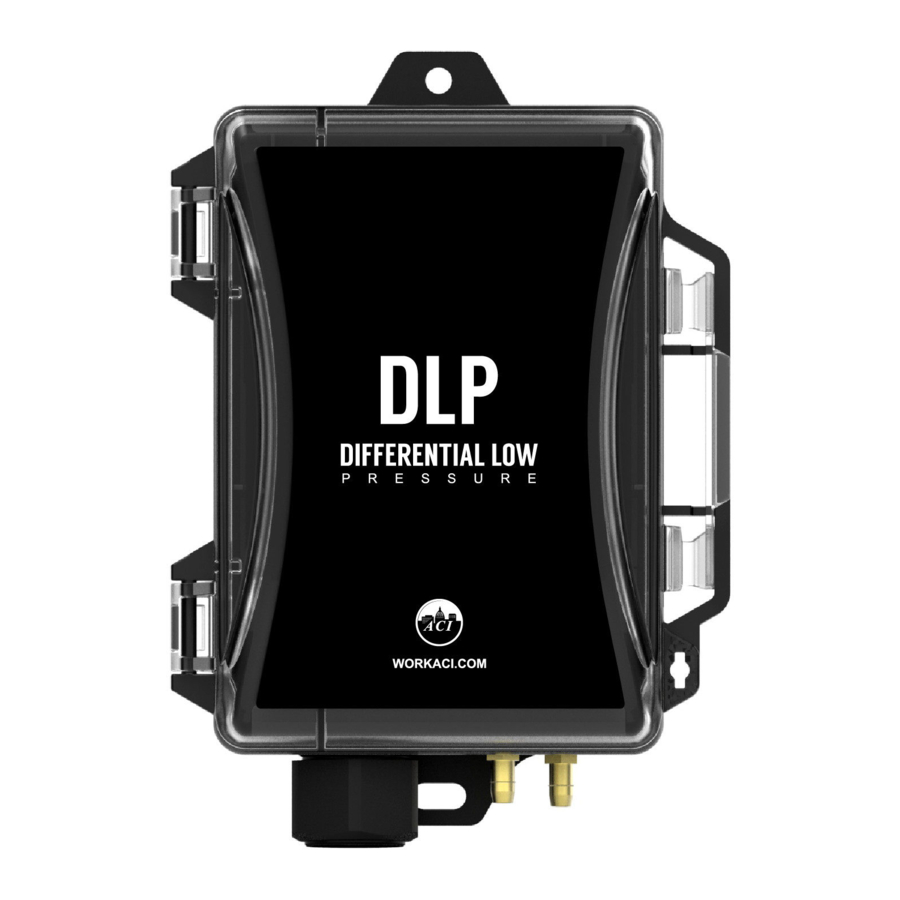
Figure 1: DLP Dimensions and Hardware
. N
EVER CONNECT OR DISCONNECT WIRING WITH THE POWER APPLIED
.
Figure 2: DIN Rail Mounting
Page 1 of 6
Installation and Operation Instructions
24
VAC
.
.
DLP Series
. D
O NOT ALLOW
.
Version : 5.0
I0000777
Advertisement

Related Manuals for aci DLP Series


Summary of Contents for aci DLP Series
- Page 1 Installation and Operation Instructions DLP Series Figure 1: DLP Dimensions and Hardware PRECAUTIONS EMOVE POWER BEFORE WIRING EVER CONNECT OR DISCONNECT WIRING WITH THE POWER APPLIED O NOT ALLOW LIVE WIRES TO TOUCH THE CIRCUIT BOARD N ISOLATION TRANSFORMER IS RECOMMENDED WHEN POWERING THE DEVICE WITH ...
-
Page 2: Pressure Connections
PITOT TUBE INSTALLATION (Optional Accessory Ordered) Slip the rubber washer over the threaded end of the pitot tube, keeping the washer as close to the threaded end as possible. Fasten the pitot into the threaded insert on the back of the enclosure. Press the rubber washer against the enclosure. Figure 3: Pitot Tube Installation TUBING SETUP WHEN PITOT TUBE IS INSTALLED Units will be shipped with silicone tubing attached to the high and low pressure barb fittings. - Page 3 Duct Mount Panel Mount Figure 5: DLP Mounting WIRING Shielded is recommended cable with 16 to 24AWG conductors. The hinged cover must be opened to connect wires to the unit’s finger push-button terminal blocks. Each DLP unit can be configured to three output signals: 4-20mA, 0-5V or 0-10V. Use the Wiring Connections (Table 1) and diagrams (Figure 7) to determine the proper wiring for your application.
-
Page 4: Zero Function
HOOSE DIFFERENTIAL ANGE BASED ON THE EXPECTED DIFFERENTIAL PRESSURE IN YOUR APPLICATION MOVE SWITCHES TO THE CORRECT POSITIONS AND THEN POWER ON THE TRANSMITTER MAXIMUM PRESSURE ACI Part No. Maximum Pressure (inWC) DLP-001-W DLP-010-W DLP-040-W AUTOMATION COMPONENTS, INC Version : 5.0... -
Page 5: Diagnostic Output
Unidirectional Mode DIP switch SW3 position five set at UNI side. DIP switch SW3 positions one and two are for Range Selection ACI Part No. SW3 Position 1: 1 SW3 Position 1: 2 Position 2: A Position 2: B... -
Page 6: Product Specifications
Table 2: Product Specifications WARRANTY SPECIFICATION The DLP Series pressure transmitters are covered by ACI’s Five (5) Year Limited Warranty, which is located in the front of ACI’S SENSORS & TRANSMITTERS CATALOG or can be found on ACI’s web site: www.workaci.com.