Table of Contents

Related Manuals for Genesis GDP1005A


Summary of Contents for Genesis GDP1005A
- Page 1 GDP1005A 10" 5-Speed Drill Press Perceuse à colonne de 10 po., 5 vitesses Taladro de pie de 10”, 5 velocidades Operator’s Manual Manuel d’utilisation Manual del operario TOLL FREE 888-552-8665 HELP LINE: www.genesispowertools.com WEBSITE:...
-
Page 2: Specifications
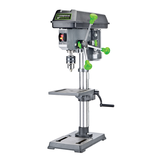
SPECIFICATIONS • Model: -------------------------------- GDP1005A • Rated Power: ------------------------- 120V~ /60 Hz, 4.1 Amp • No Load Speed: ----------------------- 5 Speeds (620, 1150, 1630, 2180, 3070 RPM) • Chuck Size: --------------------------- 5/8” (16mm) • Spindle Travel: ------------------------ 2” (50mm) • Swing: -------------------------------- 10” (254mm) • Table Movement:---------------------- 45° bevel, 360° swivel • Table Size: ---------------------------- 7-1/4” x 7-1/4” (184mm x 184mm) • Base Size: ---------------------------- 13-3/8” x 8-1/4” (340mm x 210mm) • Max. Distance from Spindle End to Surface of Table:-------- 12-3/16” (310mm) • Max Distance from Spindle End to Surface of Base: --------- 1 7-1/4” (438mm) • Max Distance from Spindle Axis to Surface of Column: ----- 5 ” (127mm) • Net Weight: ------------------------------------------------- 49.5 Lbs Includes: Chuck Key, 2 Allen Wrenches and 2 “AAA” Batteries for Work Light WArNINg: To reduce the risk of injury, user must read and understand this operator’s manual before operating this tool. -
Page 3: Electrical Safety
Do not operate power tools in explosive atmospheres, • such as in the presence of flammable liquids, gases, or dust. Power tools create sparks which may ignite the dust or fumes. Keep bystanders, children, and visitors away while operating a power tool. • Distractions can cause you to lose control. ELECTRICAL SAFETY Power tool plugs must match the outlet • . Never modify the plug in any way. Do not use any adapter plugs in any earthed (grounded) power tools. Double insulated tools are equipped with a polarized plug (one blade is wider than the other). This plug will fit in a polarized outlet only one way. If the plug does not fit fully in the outlet, reverse the plug. If it still does not fit, contact a qualified electrician to install a polarized outlet. Do not change the plug in any way. Double insulation eliminates the need for the three wire grounded power cord and grounded power supply system. -
Page 4: Extension Cords
This will ensure that the safety of the power tool is maintained. Service your power tool periodically • . When cleaning a tool, be careful not to disassemble any portion of the tool since internal wires may be misplaced or pinched. SAVE THESE INSTRUCTIONS EXTENSION COrDS grounded tools require a three wire extension cord Double insulated tools can use either a two or three wire extension cord. As the distance from the power supply outlet increases, you must use a heavier gauge extension cord. using extension cords with inadequately sized wire causes a serious drop in voltage, resulting in loss of power and possible tool damage. Refer to the table shown below to determine the required minimum wire size. The smaller the gauge number of the wire, the greater the capacity of the cord. for example: a 14-gauge cord can carry a higher current than a 16-gauge cord. When using more than one extension cord to make up the total length, be sure each cord contains at least the minimum wire size required. If you are using one extension cord for more than one tool, add the nameplate amperes and use the sum to determine the required minimum wire size. 10" Drill Press Operator’s Manual GDP1005A... -
Page 5: Specific Safety Rules For Drill Presses
guidelines for Using Extension Cords • If you are using an extension cord outdoors, be sure it is marked with the suffix “W-A” (“W” in Canada) to indicate that it is acceptable for outdoor use. • Be sure your extension cord is properly wired and in good electrical condition. Always replace a damaged extension cord or have it repaired by a qualified person before using it. • Protect your extension cords from sharp objects, excessive heat, and damp or wet areas. Recommended Minimum Wire Gauge for Extension Cords (120 Volt) Nameplate Extension Cord Length Amperes 25 Feet 50 Feet 75 Feet 100 Feet 150 Feet 200 Feet (At Full Load) 0–2.0 2.1–3.4 3.5–5.0... -
Page 6: Symbol Description
Kilograms Wear safety glasses, ear protection and respiratory protection Hours Do not dispose with house- hold waste Revolutions per minute Do not touch the running blade Strokes per minute Do not use in wet conditions oscillations per minute Do not put battery in fire .../min Per minute Battery cannot exceed 59° C This symbol designates that this product is listed with U.S. and Canada requirements by CSA group. 10" Drill Press Operator’s Manual GDP1005A... - Page 7 KNOWINg YOUr 10" DrILL PrESS FIG 1 1. Pulley Housing Cover 9. Table Support 17. LED Work Light 2. Motor 10. Column 18. Depth Scale 3. oN/off Switch 11. Column Ring 19. Bevel Scale 4. Chuck 12. feed Handle 20. feed Return Spring and Cover 5. Spindle 13. Tension Lock Screw 21. Base 6. Crank Handle 14. Motor Pulley 22. B attery Compartment for 7. Table Support Lock Handle 15. Spindle Pulley Work Light 8. Table 16. Belt...
- Page 8 Always be sure that the tool is switched off and unplugged from the power FIG 3 source before adjusting, adding accessories, or checking a function on the tool. ATTACHING COLUMN TO BASE (FIG 3) 1. Set the Base (D) on a level, flat surface. 2. Place the Column & Support (C) on the Base (D), align the three holes in the column support with the holes in the base. 3. Install a set of Bolts and Washers (N) in each column support hole and tighten with a wrench. 10" Drill Press Operator’s Manual GDP1005A...
-
Page 9: Installing The Table Assembly
INSTALLING THE TABLE ASSEMBLY FIG 4 (FIG 4,5) 1. Insert the rack (K) into the geared groove of the table support (9). Make sure the rack is engaged with the teeth of the gear. 2. Slide the table support and rack assembly down together onto the column (C). Insert the bottom edge of the rack into the lip of the column support (C1). Hold its position. 3. Place the column ring (L) bevel side down over the rack. FIG 5 Tighten the set screw (L1) with 4mm Allen wrench provided to hold the rack in position. NOTE: Make sure there is enough clearance to allow the table to rotate around the column. The ring should sit loosely over the rack. 4. Insert the table support crank handle (H) into the worm shaft (B2). Make sure the set screw is aligned to the flat of the shaft and as close to the table support as possible. Tighten the set screw. 5. Position the table in the same direction as the base. Tighten the table support lock handle (7). INSTALLING HEAD ASSEMBLY, FEED HANDLES AND CHUCK (FIG 6, 7) 1. With the aid of a second person, carefully lift the head assembly (A) onto the column top. - Page 10 1. Loosen the bevel lock bolt (B4) with a wrench. 2. Tilt the table (8) to the desired angle, using the bevel scale (19) as a basic guide. FIG 12 3. Re-tighten the bevel lock bolt (B4). 4. To return the table to its original position, loosen the bevel lock bolt. Realign the bevel scale (19) to the 0° setting. 5. Tighten the bevel lock bolt (B4) with the wrench. SETTING DRILL DEPTH (FIG 13) The drill depth scale (18) is located on the hub (A4). See fIG 13. The scale pointer (A5) indicates the spindle travel distance. To stop the drill at a specific depth for consistent and repetitive drilling: 1. Loosen the depth scale lock (A6) FIG 13 10" Drill Press Operator’s Manual GDP1005A...
-
Page 11: Operation
2. Rotate the scale hub (A4) until pointer (A5) is aligned to the desired depth on the scale. 3. Tighten the depth scale lock (A6). The chuck will stop after traveling downward to the distance selected. ADJUSTING THE RETURN SPRING (FIG 14) The return spring is adjusted at the factory and should not need further adjustment. If adjustment is deemed necessary: 1. unplug the machine from the power source. 2. Loose the two jam nuts (A7). Do not remove. FIG 14 3. firmly hold the coil spring cover (A8). Pull out the cover and FIG 15 rotate until the pin (A9) on motor head engages the next notch in the cover. Turn the cover clockwise to decrease tension and counterclockwise to increase tension. 4. Tighten two jam nuts. Do not over-tighten. The jam nuts should be tightened against each other. SQUARING THE TABLE TO THE HEAD (FIG 15) 1. Install a 3" long drill bit into the chuck (4) and tighten. - Page 12 GENERAL DRILLING INSTRUCTIONS 1. using a clamping device, secure the workpiece to the worktable. If drilling a through hole, place a piece of backup material (wood, plywood, etc.) on the table underneath the workpiece to prevent splintering on the underside of the workpiece. To protect the top surface of the workpiece, use a piece of scrap wood between the vise and the workpiece. 2 Select the proper drill bit based on the hole size desired. for large holes, drill a pilot hole first, using a smaller size bit. 3 Select and set the recommended spindle speed. 4. Set table assembly to desired height. 5. If desired, set feed shaft at desired spindle depth. Refer to "Set Drill Depth" section. 6. Make sure the work table is free of all loose objects and the bit is not in contact with the workpiece. 7. Plug in power supply and turn switch oN. Make sure spindle rotates freely. 8. Slowly lower drill bit into workpiece. Do not force the bit; let the drill press do the work. 9. once the hole is completed, allow the spindle to return to its normal position. WArNINg: Make sure the chuck key is removed from the chuck before starting any drilling operation. 10" Drill Press Operator’s Manual GDP1005A...
-
Page 13: Maintenance
LUBRICATION 1. Lower spindle to maximum depth and oil moderately once every three months. 2. oil the column lightly every two months. TWO-YEAr WArrANTY This product is warranted free from defects in material and workmanship for 2 years after date of purchase. This limited warranty does not cover normal wear and tear or damage from neglect or accident. The original purchaser is covered by this warranty and it is not transferable. Prior to returning your tool to store location of purchase, please call our Toll-free Help Line for possible solutions. ACCESSORIES INCLUDED IN THIS KIT ARE NOT COVERED BY THE 2 YEAR WARRANTY. TOLL-FrEE HELP LINE 888-552-8665 for questions about this or any other GENESIS Product, please call Toll-free: www.genesispowertools.com or visit our web site: ©richpower Industries, Inc. All rights reserved Richpower Industries, Inc. 736 Hampton Road Williamston, SC 29697 Printed in China, on recycled paper... - Page 14 Richpower Industries, Inc. 736 Hampton Road Williamston, SC USA www.richpowerinc.com 2016..02 v.01...
Need help?
Do you have a question about the GDP1005A and is the answer not in the manual?
Questions and answers