Table of Contents
Advertisement
Pandora Smart Moto v2 is a security-service system specially designed for motorcycles.
It is a complex engineering solution, which includes security system, telemetry, remote and
automatic engine start and various service options.
When building the Pandora Smart Moto v2 we were using the most up-to-date electronics from
world's best manufacturers. The device is built using high-precision mounting and control machinery,
thus we guarantee highest possible quality, reliability and stable technical characteristics for the whole
operation period.
The system is built for your convenience: its ergonomic, reliable, has the highest security and service
characteristics, 3 years warranty. We are happy to provide any support we can – feel free to use our
online support.
This device has limited external factors resistance. It should not be operated in temperatures outside -40 to +85° C range.
Our web site: www.pandorainfo.com
Customer support: support@pandorainfo.com
Pandora would like to thank you for
choosing our service-security system
Product is in conformity with Electromagnetic Compatibility
Directive EMC 2004/108/EC and R&TTE Directive 1999/5/EC
Pandora Smart Moto v2
Advertisement
Table of Contents

Subscribe to Our Youtube Channel
Related Manuals for Pandora SMART MOTO V2


Summary of Contents for Pandora SMART MOTO V2
- Page 1 It is a complex engineering solution, which includes security system, telemetry, remote and automatic engine start and various service options. When building the Pandora Smart Moto v2 we were using the most up-to-date electronics from world’s best manufacturers. The device is built using high-precision mounting and control machinery, thus we guarantee highest possible quality, reliability and stable technical characteristics for the whole operation period.
-
Page 2: Table Of Contents
Table of contents General information System set Read before using PIN-codes of the system System modules layout Owner’s personal card External VALET button Base unit System signals System functions and modes Security mode Owner authorization devices and functions Checking the number of paired devices Immobilizer radio tag Functions of the button Indication of the SEND LED... - Page 3 Online service and mobile applications Control the system Arming Disarming PANIC mode Vehicle search function Service mode Control of the system in case of emergency Emergency disarming Temporary deactivation of anti-theft functions Programming the systems Entering/Exiting programming mode Programming table Additional devices Warranty obligations Installation certificate...
-
Page 4: General Information
GENERAL INFORMATION System set 1. User manual 2. Owner’s personal card 3. Radio tag BT-760 4. Base unit 5. External VALET button 6. External temperature sensor 7. Reed sensor 8. Blocking relay 9. Piezo siren PS-330 10. Wires 11. Fastening kit 12. -
Page 5: Read Before Using
Read before using Carefully read this manual before starting installation and using the security-service system. Pay attention to text marked with he securiTy and TelemeTric sysTem is a complex Technical producT ysTem insTallaTion and configuraTion musT be carried ouT only by a skilled professional eaTures and sysTem modes conTrol of The vehicles zones depends on The Type of connecTion and sysTem seTTings original vehicle operaTion logic and Trim... -
Page 6: Pin-Codes Of The System
PIN-codes of the system The “Secret PIN-code“ CANNOT BE CHANGED (is written on the “Owner’s personal card”) The “Service PIN-code” (default value is 1-1-1-1) The “Guest PIN-code” (default value is 1-2-3-4) The “Immobilizer PIN-code” (is used for the Validator (pin-to-drive) function) pin- T is recommended ThaT you will wriTe down The changed or creaTed values of all codes... -
Page 7: Owner's Personal Card
Owner’s personal card rase The proTecTive layer carefully o noT use any sharp objecTs To avoid damaging of hidden informaTion under The proTecTive layer LOGIN PASS The owner’s personal card contains private information 1070000000 / Y34aC4vJ under a protective layer: •... -
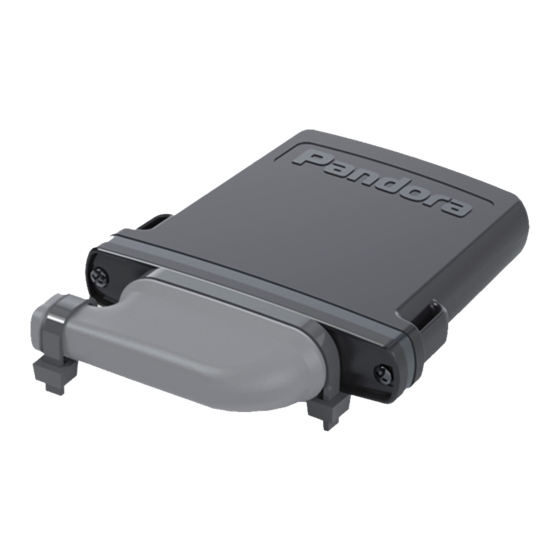
Page 8: Base Unit
Built-in battery to notify an owner in case of power disconnection in armed mode. The battery will be charged automatically when engine is running. Built-in micro-USB port – update and configuration of the system using a PC and Pandora Alarm Studio. -
Page 9: System Signals
System signals SOUND AND LIGHT SIGNALIZATION SIGNALS DESCRIPTION Arming 1х /1х Disarming 2х /2х Enabling Service mode 1х Disabling Service mode 2х Battery in a radio tag is discharged warning (when turn on ignition) 3х / 3 times There is no any authorization device warning (when turn on ignition) 4х... - Page 10 LED INDICATOR SIGNALS SIGNALS DESCRIPTION THE SYSTEM IS ARMED Short red flashes System is armed Short green flashes System is armed (an authorization device is in the coverage zone) Fast red flashes Alarm THE SYSTEM IS DISARMED Faded System is disarmed System is preparing for automatic or delayed arming Green System is in service mode...
-
Page 11: System Functions And Modes
SYSTEM FUNCTIONS AND MODES Security mode The system confirms arming with 1х sound 1х light signals. When the system is armed, the system monitors security zones with separated warning and alarm level of triggering: • Warning mode - this mode activates when there is a slight impact on the shock sensor or additional senor. - Page 12 NOTIFICATIONS VEHICLE/SYSTEM ZONES CONTROLLED ZONES SECURITY ZONES Voice Push External temperature Engine temperature On-board voltage Shock sensor (alarm) Shock sensor (warning) Tilt sensor (alarm) Motion sensor (alarm) Ignition (alarm) Brake (alarm) Clutch (alarm) Trunk (alarm) Additional sensor (alarm) Additional sensor (warning) PA N D O R A S M A R T M OTO V 2...
-
Page 13: Owner Authorization Devices And Functions
Owner authorization devices and functions Authorization devices Authorization devices are Bluetooth devices paired with the system (radio tags, remote control D030, mobile phone with the app). The devices are used to recognize an owner in the radio coverage zone of the base unit to arm/disarm the system (Hands Free mode) and to implement immobilizer or Anti- Hi-Jack functions. -
Page 14: Checking The Number Of Paired Devices
Multi-button code immobilizer (pin-to-drive) Multi-button code immobilizer (pin-to-drive) is a function that allows disarming, disabling blocking and controlling service mode and time channels using original vehicle controls (button, lever or pedal) and a pre-programmed PIN-code (the “Immobilizer PIN-code”). AN EXAMPLE OF USING THE FUNCTION •... -
Page 15: Immobilizer Radio Tag
IMMOBILIZER RADIO TAG A radio tag is a device used to control a vehicle/system. The tag is also used as an authorization device for “Immobilizer/Anti-Hijack/HandsFree” modes. It works in the Bluetooth coverage zone. The radio tag has: SEND - 2.4GHz frequency, BLUETOOTH 4.2 LOW ENERGY protocol - control button - LED indicator SEND... -
Page 16: Indication Of The Send Led
If it is so, the tag can be operated as usually. Updating firmware of the tag • Download the Pandora BT application (for Android or iOS devices equipped with a Bluetooth 4.0 Low Energy or higher module). • Open the mobile app Pandora BT. -
Page 17: Control The System By A Phone
CONTROL THE SYSTEM BY A PHONE or The correcT operaTion of The funcTions an owner should moniTor The sTaTus balance of The card , gsm insTalled in The sysTem f The card is blocked or defecTive funcTions of The sysTem will be unavailable Call the system’s phone number. - Page 18 2. Dial 500*. 3. The system will confirm: ‘Current coordinates are sent via text message’ and will send text message with coordinates and a web link to a map to your phone. To end the session, hang up the phone.. Request GSM balance 1.
-
Page 19: Changing Settings Via A Phone
Changing settings via a phone Owner's number -> # Changing guest PIN-code Phone Additional number settings settings Additional owner's number -> # Entering as guest Second additional owner's Set threshold voltage for sending number -> # text message Account balance inquiry number -> # Settings of the warning level of the shock sensor sensitivity Sensor... - Page 20 Disarm the system, call the system number, wait for the answer, switch on the ignition for 1-3 seconds (but no more than 5 seconds), then switch it off. The system will enter the settings mode. An example of changing the owner’s system number: 1.
-
Page 21: System Installation
SYSTEM INSTALLATION General installation requirements • Install base unit in hidden places where access is difficult. • Install securely each system’s component, as conditions of the vehicle standard operation can harm functionality of the alarm system and cause damage to the vehicle original systems, including the elements of safety in motion. -
Page 22: Wiring Description
Connector Х1 (micro-USB) This connector is used to configure and update the system via a USB cable connected to a computer with Pandora Alarm Studio. Connector Х2 (Main connector) The main connector has multi-function inputs (INP) and outputs (CH) with the factory-preset logic. - Page 23 • Wire №10 | Purple | 2А | CH5 — Factory default logic is “Siren” and “Beeper”. Connect this wire to to (+) control wire of the siren. • Wire №11 | White-green | LED/VALET — Connect this wire to the black wire of the LED/VALET button.
- Page 24 WARNING! All power circuits of the front side of the unit (the side with additional devices that are not the “Pandora” sign). powered through the base unit of WARNING! Fixate the protective cap the system should have their own using clamps when the installation is fuses.
-
Page 25: Wiring Diagram
INP2/CH4 – Output “Blocking NC” Green/Black max 20A/nom 10A INP1 – Input “Ignition” Green/Red 87 87a max 20A/nom 10A sensor (engine) NО Green GROUND (-) +12V POWER (+12V) External SMART MOTO Pandora temperature sensor Wiring diagram... -
Page 26: Online Service And Mobile Applications
Visit the website or open the mobile app to create an account - Web-service: • https://pandora-on.com Mobile apps: • Pandora Pro for iOS is available in the AppStore; • Pandora Online for Android is available on the Play Market (Google Play). v4.4; os v10. inimum requiremenTs ndriod You will create the data to sign in: LOGIN –... - Page 27 Login After completing of the registration process, you can login to the online service via a computer’s web browser or via the mobile apps Pandora Pro or Pandora Online. Use your previously created login/ password to login Adding a system to your account The created account can support up to 3 telemetry systems.
- Page 28 III. PAIR A MOBILE PHONE Turn on Bluetooth on your mobile phone and open the mobile application. Go to : Settings -> Bluetooth control -> Bluetooth device/ Not specified (Android)» -> + (iOS)/ Add (Android». Select the found system in the search window, the system and the mobile device will be automatically paired. The system will confirm pairing with the series of green and red flashes of the LED and a sound signal of the siren.
-
Page 29: Control The System
The icon of the current system mode will be changed Online-service – Login to the PANDORA-ON.COM, when the system is online (there is an Internet connection) press the button on the control panel. The icon of the current system mode will be changed Phone –... -
Page 30: Disarming
The icon of the current system mode will be changed Online-service – Login to the PANDORA-ON.COM, when the system is online (there is an Internet connection) press the button on the control panel. -
Page 31: Panic Mode
VALET button – Enter the ”Secret PIN-code” (see the ”Emergency disarming using the VALET button” section). PANIC mode If your car or you are in danger and you want to draw attention to your car, you can use PANIC mode. In this mode the siren will sound will flash repeatedly for 30 seconds. -
Page 32: Service Mode
(until the third flash of the LED), release the button «SEND». Mobile applications Pandora Online and Pandora Pro – To activate/deactivate service mode, open the mobile application. When the system is online (there is an Internet or Bluetooth connection), press and hold the button on the control panel until the scale is fully loaded. -
Page 33: Control Of The System In Case Of Emergency
CONTROL OF THE SYSTEM IN CASE OF EMERGENCY The system has emergency ways to deactivate security and anti-hijack functions (using the VALET button and the “Secret PIN-code”) in case of loss or failure of control devices or in case of discharge of a battery (when you cannot replace it or charge). -
Page 34: Emergency Disarming
• Enter the fourth digit • Press the button the number of times equal to the fourth digit. Pauses between presses should not exceed 1 second. Each pressing will be confirmed with an orange LED indicator flash. The correct input will be confirmed with the series of green and red flashes of the LED indicator. - Page 35 Emergency deactivation of anti-theft functions Emergency control of the anti-theft functions is possible only when the system is disarmed, the ignition is off, service mode is deactivated, a vehicle battery is charged. Enter the “Secret PIN-code” or the “Service PIN-code” (default value is 1-1-1-1) to put the system in programming mode To manage Immobilizer and Anti-Hi-Jack To manage Immobilizer and Anti-Hi-Jack...
-
Page 36: Programming The Systems
PROGRAMMING THE SYSTEM The system can be configured by the Pandora Alarm Studio app. Some settings can be changed in programming table only. To change the system settings or program the system using a computer or VALET button, the system should be in programming mode. -
Page 37: Entering/Exiting Programming Mode
Entering/Exiting programming mode You can enter the programming mode only if the base unit is powered form a USB cable or the main power supply is connected, the ignition is off, the system is disarmed and service mode is off. To enter programming mode, enter the “Service PIN-code”... -
Page 38: Programming Table
№5 – Pairing an additional module RHM-03BT/PS-331BT/PS-332BT (1 item) №6/№7 Pairing a radio relay BTR-101 (2 items) №8 – Pairing a GPS-receiver NAV-035 BT №10 – Pairing a telemetry module Pandora Eye Pro №11 – Programming and configuring an “Immobilizer PIN-code” • 1 №13/15 –... - Page 39 Level №0 – Entering a level After entering programming mode, the system waits for level input – “Level 0 Entering a level”. Enter a desired level using the VALET button (see the programming table) to change settings or parameters: • To enter a level, press the VALET button the number of times equals to the desired level number, pauses between presses should not exceed 1 second.
- Page 40 Enter the programming level №2: • Enter the first digit of the code using the VALET button. Press the button the number of times equals to the first digit. Pauses between presses should not exceed 1 second, every pressing will confirm with an orange LED indicator flash.
- Page 41 • №11.1 - Entering the PIN-code Program the immobilizer deactivation PIN-code using the selected button or buttons on this sublevel. The code can consist of one or more memory cells, each memory cell can store a sequence of pressing each of the five selected immobilizer buttons. The code is entered by pressing the selected buttons for at least 1 second.
-
Page 42: Additional Devices
ADDITIONAL DEVICES Remote control D-030 is a two-way short-distance communication device designed to control a security system and receive information about its state. The remote control can be used as an owner authorization device. CONTROL COMMANDS Arming/Disarming | Trunk | Remote engine start | Engine pre-heater STATUSES Состояние... - Page 43 Door sensor DMS-1OO BT is a wireless device designed to monitor internal or external perimeter state: any security zone can be assigned to the Hall/shock/tilt sensor state; temperature monitoring. The sensor can be installed on a door, hatch, trunk, trail, garage door 2.4GHz radio interface (BLE 4.2) | Hall sensor | Temperature sensor | Shock/tilt sensor | CR123a battery Piezo siren PS-331 BT / PS-332 BT are wireless device for sound...
-
Page 44: Warranty Obligations
WARRANTY OBLIGATIONS Manufacturer guarantees correct operation of the service-security system if exploitation, installation, storage and transportation conditions described in this manual were met. The system should only be used according to installation scheme and user manuals. The system is meant to be installed by the professional car electronics installers. The installer should fill in installation certificate that is included in this manual. - Page 45 U S E R M A N UA L...
- Page 46 PA N D O R A S M A R T M OTO V 2...
-
Page 47: Installation Certificate
Car specifications: Car model____________________________________________ Type _____________________ Id number (VIN)_________________________________________________________________ Registration number_____________________________________________________________ Security system specification: Model Pandora Smart Moto v2 Serial number______________________________ Service center name, full address and installer’s stamp ____________________________________________________________________________________ ____________________________________________________________________________________ Signature_____________________/___________________________________/... -
Page 48: Acceptance Certificate
ACCEPTANCE CERTIFICATE Model Pandora Smart Moto v2 is in conformity with Electromagnetic Compatibility Directive EMC 2004/108/EC and R&TTE Directive 1999/5/EC. Serial number ______________________________ Date of production__________________________ Responsible person’s signature (stamp) Packager_____________________________________________________________________________ Signature (personal stamp) WARRANTY CARD Model Pandora Smart Moto v2 Serial number ________________________________________________________________________ Date of purchase «____»...
Need help?
Do you have a question about the SMART MOTO V2 and is the answer not in the manual?
Questions and answers