
Related Manuals for Axminster Trade AT310T2


Summary of Contents for Axminster Trade AT310T2
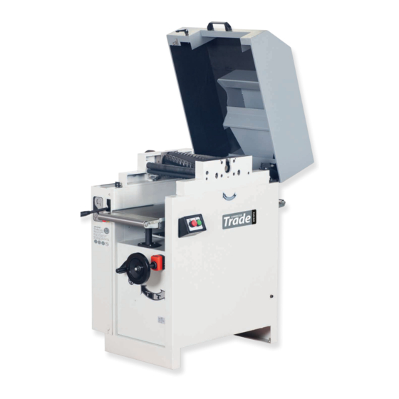
- Page 1 Code 106202 Original Instructions AT310T2 310mm Spiral Cut Thicknesser AT&M: 07/05/2019 BOOK REF:104113...
-
Page 2: Eu Declaration Of Conformity
EN 55014-2:2015 EN 861:2007+A2 EN 61000-3-2:2014 Thicknesser Type EN 61000-3-3:2013 AT310T2 Model and conforms to the machinery example for which the EC Type-Examination Certificate No BM 50314336, AE 50390663 has been issued by Laizhou Planet Machinery Co., Ltd. Signed at: Yutai West Street Laizhou, Shandong 261400 China (Mainland) and complies with the relevant essential health and safety requirements. -
Page 3: What's Included
What’s Included Quantity Item Model Number AT310T2 1 No 310mm Spiral Cut Thicknesser 1 No 7mm, 5.5mm Spanner 1 No Instruction Manual edge when required. If one or more cutters is damaged, then Introduction simply replace. Each edge lasts up to 10 times the expected... -
Page 4: General Instructions For 230V Machines
General Instructions for 230V Machines • Carry out a final check e.g. check the cutting tool The following will enable you to observe good working practices, keep yourself and fellow workers safe and maintain is securely tightened in the machine and the correct your tools and equipment in good working order. -
Page 5: Specification
Specification Code 106202 Model AT310T2 Rating Trade Power 2.2kW 230V 1ph Feed Speed 8m/min Cutterblock Speed 4,050rpm Cutterblock Diameter 95mm Noise Level 85dB Max Thicknesser Capacity 310 x 220mm Max Depth of Cut Knives 78 XTCT Spur Cutters Length of Table... - Page 6 Assembly The planer Thicknesser comes 98% assembled. It is Fig 02-03-04 enclosed in a packing case with all the accessories. Having removed the top and the sides of the packing case, remove all the components from the machine, place safely aside. 1.
-
Page 7: Machine Dimensions
Machine Dimensions 1,050mm... -
Page 8: Illustration And Parts Description
Illustration and Parts Description Thicknessing hood Spiral cutter block Infeed table Autofeed engage and disengage lever Main frame Thicknessing table rise ON/OFF control assembly and fall control wheel Digital thicknessing display... - Page 9 Illustration and Parts Description ON/OFF Control The Digital Thickness Display, will give an accurate visual indication of the amount you are adjusting the thicknessing table in 0.10mm increments. Autofeed lever (A) to engage the thicknessing fuction Lift & Shift locking handle to secure Emergency stop (B), rotate the button to unlock the switch the thicknessing cover Rise and fall clamping handle (A), in the locked postion...
- Page 10 Illustration and Parts Description Thicknessing hood in the closed position Hose support hook Extraction outlet Outfeed table Table extension assembly Motor/Drive access panel...
- Page 11 Illustration and Parts Description Cutter block drive assembly Thicknesser cover safety micro switch Table column grease nipple Drive belt threaded tension stop...
- Page 12 Illustration and Parts Description Four sided blade Pressure roller Spiral cutter block Anti-kick back fingers Drive roller Clamping Hex screw Four sided blade Pressure roller Drive roller Anti-kick back fingers...
-
Page 13: Positioning The Machine
Positioning the Machine Allow sufficient clearance all round the machine Ascertain the orientation of the machine and move it to its desired position in the workshop. Ensure that the machine is positioned to allow sufficient clearance all round to cater for the maximum length of timber you wish to machine. - Page 14 Operating Instructions Setting the Machine for Thicknessing 1. Visit the HSE (Health and Safety Executive) website for the correct safe operating procedures. HSE Health and Safety Executive To operate the machine correctly, it is recommended to read the HSE (Health and Safety Executive) website at www.hse.gov.uk.
- Page 15 Operating Instructions Fig 17 Changing the Spiral Cutter Block Blades DISCONNECT THE MACHINE FROM THE MAINS SUPPLY BEFORE CONTINUING! The spiral cutter block has four rows of square cutters running around its circumference. There are 84 square cutters in total on the 12inch cutter block.
-
Page 16: Maintenance
Maintenance Fig 22 DISCONNECT THE MACHINE FROM THE MAINS SUPPLY BEFORE CONTINUING! Dust extractor Daily Check that thicknessing table is clean, not coated with resin etc. Apply a proprietary cleaner/lubricating agent such as ‘Wax & Polish Remover’ (1) and ‘Lubricating Wax’ (2). Check the cable and the plug for damage or defects. - Page 17 Maintenance Clean out any build up of debris around the edges of the thicknessing table Monthly Carry out the ‘Weekly’ checks. Access panel Remove the machine’s motor/drive access panel by removing locating pin the Phillips screws on either side of the panel. Lift away the panel and place to the side, see fig 27-28-29-30.
- Page 18 Maintenance Fig 31-32 Fig 34-35 Un-lock Autofeed wheel Autofeed assembly Drive shaft Autofeed wheel Autofeed wheel disengaged Autofeed wheel engaged Drive Belt Tension Check the condition and tension of the drive belt, see fig 33. Remove the motor/drive access panel, if not done so already. Check the tension of the belt by pushing the belt, there should Check the autofeed engage and disengage function, see fig be a deflection of between (12-20mm).
- Page 19 Maintenance Table Lifting Column Table Rise & Fall Screw Mechanism 1. To the side of the lifting column housing there is a grease It it recommended to grease the tables rise and fall screw nipple to lubricate the inner column. If you notice after a mechanism once or twice a year.
-
Page 20: Exploded Diagram/Parts List
Exploded Diagram/Parts List... - Page 21 Exploded Diagram/Parts List DESCRIPTION SOCKET HEAD CAP SCREW M8x35 BODY WASHER 8 SMALL PLATE SOCKET HEAD CAP SCREW WASHER M6x35 SCREW M5x8 NUT M6 RIGHT COVER PLATE SUPPORT PLATE SCREW M5x8 OIL CUP M10 SCREW M10x16 GUIDING BODY MOTOR SPRING WASHER 8 SCREW M8X25 SCREW M8X20 NUT M8...
- Page 22 Exploded Diagram/Parts List LOCK NUT M10 ROD II WASHER 6 WASHER 10 SCREW M8x25 BOLT M6x10 GEAR BOX SELF-LOCK NUT M6 TENSION SYSTEM PIN 4X18 NUT M8 TENSION SPRING LOCATING SLEEVE PIN ROLL TENSION SUPPORT PLATE ROLL SHAFT PIN ROLL BEARING 6303-2Z COVER PLATE SPLIT WASHER 4...
- Page 23 Exploded Diagram/Parts List...
-
Page 24: Wiring Diagram
Wiring Diagram... - Page 25 Notes...
- Page 26 Notes...
- Page 27 Notes...
- Page 28 The Axminster guarantee is available on Craft, Trade, Engineer, Air Tools & CNC Technology Series machines Buy with confidence from Axminster! So sure are we of the quality, we cover all parts and labour free of charge for three years! For more information visit axminster.co.uk/3years The packaging is suitable for recycling.
Need help?
Do you have a question about the AT310T2 and is the answer not in the manual?
Questions and answers