Advertisement
Table of Contents
- 1 Table of Contents
- 2 Table of Contents
- 3 SECTION 1: General Information
- 4 To Service Personnel
- 5 Limited Warranty
- 6 Introduction to Audioscopes
- 7 Use of the Audioscope (Screening)
- 8 SECTION 2: Service
- 9 Intent of Service Manual
- 10 Lists of Tools/Fixtures/Documents for Service 2.3A
- 11 Audioscope 3 S/N>=970000 2.3C
- 12 Training
- 13 Calibration (Single Level 23020,23000,23040)
- 14 Troubleshooting Audioscope 3 S/N <=969999
- 15 Charging Stand
- Download this manual
®
Service Manual
AudioScope™/ AudioScope 3™
Screening Audiometers
Single Hearing Level Models: 23020, 23000, 23040
Three Hearing Level Model 23300
Charging Stand 71123
Charging Transformers: Australia - 71036, Europe - 71032, Japan -71030,
United Kingdom 71034, United States - 71040
Welch Allyn, Inc.
4341 State Street Road
P.O. Box 220
Skaneateles Falls, NY 13153-0220
PN: 230260 Rev. B
Copyright 2004
Advertisement
Table of Contents

Related Manuals for Welch Allyn AudioScope


Summary of Contents for Welch Allyn AudioScope
- Page 1 ® Service Manual AudioScope™/ AudioScope 3™ Screening Audiometers Single Hearing Level Models: 23020, 23000, 23040 Three Hearing Level Model 23300 Charging Stand 71123 Charging Transformers: Australia - 71036, Europe - 71032, Japan -71030, United Kingdom 71034, United States - 71040 Welch Allyn, Inc.
- Page 3 Document Added Soldering 1001574 6/17/04 Soldering Temperatures Drawings and/or illustrations and/or part numbers in this document are for reference only. For the most current revision call the Welch Allyn Customer Service phone number listed in Section 1. - 3 -...
-
Page 4: Table Of Contents
Calibration (Multi Level 23300) s/n <=969999 34-35 Calibration (Multi Level 23300) s/n >=970000 36-37 SECTION 3: Troubleshooting 23300 Troubleshooting AudioScope 3 s/n <=969999 Troubleshooting AudioScope 3 s/n >=970000 SECTION 4: Disassembly and Repair, AudioScope 3 Handle 43-45 Charging stand - 4 -... -
Page 5: Table Of Contents
SECTION 5: Drawings/ Test Specifications Manilla Pockets contain 17" x 22" drawings. Drawing# Description Original Size/#sheets A02030 Repair Calibration Spec. for AudioScope II B/1 of 1 A00277 Audiometer Handle Test Specifications D/1 of 1 A00984 P.C.B. Test Spec AudioScope II... -
Page 6: Section 1: General Information
Section 1: General Information... -
Page 7: To Service Personnel
Read and understand the AudioScope operating instructions manual pn. 230231- 2. The information in this Service Manual is subject to change without notice and should not be construed as a commitment by Welch Allyn. Welch Allyn assumes no responsibility for any errors that may appear in this manual. -
Page 8: Limited Warranty
______________________________________________________________________ 1.2 Limited Warranty Welch Allyn warrants the AudioScope, when new, to be free of defects in material and workmanship and to perform in accordance with the manufacturer's specifications for a period of one year from the date of purchase from Welch Allyn or its authorized distributors or agents. -
Page 9: Introduction To Audioscopes
AudioScope II) There are two versions of this second type. AudioScope3 pn 23300 - 20, 25, 40 dB (1000 Hz PT) The original version of the AudioScope 3 (three hearing level) up to and including serial number 969999 utilizes an ASIC module. This instrument is calibrated by adjusting miniature potentiometers on the printed circuit board. - Page 10 All previous models were calibrated using mechanical potentiometer. Calibration of all types of AudioScopes is explained in this manual. If the ASIC fails on an AudioScope 3, the whole board will be replaced with the new board containing the digitally adjustable Microcontroller. This board will fit the AudioScope3 with no modifications.
- Page 11 ____________________________________________________________________ 1.3 Introduction to AudioScopes AudioScope 3 Handle Controls and features are shown in the figure below. - 11 -...
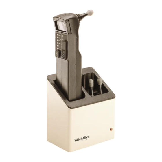
- Page 12 ____________________________________________________________________ 1.4a Basic System Description There are three components to the Welch Allyn AudioScope: the hand held AudioScope handle, the Charger stand and transformer. 1.4b AudioScope Charging Stand The charging stand holds the handle and specs and is the interface between the Handle and the charging current of the wall transformer.
-
Page 13: Use Of The Audioscope (Screening)
_____________________________________________________________________ 1.5 Use of the AudioScope (Screening) Read pg. 6-8 of Operating Instructions pn230231-2 (shown below) for full details of the screening procedure. Note: The following excerpt is only an outline intended for general familiarization by service personnel. This outline is not intended to replace above referenced Operating Instructions pn 230231-2. - Page 14 _____________________________________________________________________ 1.5 Use of the AudioScope (Screening) continued Turn AudioScope3 "ON" by sliding the selection switch to the desired screening level. Instruct patient to respond appropriately to sound. Insert the tip of the speculum into the ear canal. Position the tip so that the tympanic membrane or a portion of it can be visualized.
- Page 15 Single Hearing Level AudioScope NOTE: Since these models of AudioScopes are well over ten years old, the circuitry is no longer available. If this circuitry fails, the Single Level AudioScope is no longer repairable. Recalibrations CAN be performed if the unit is functioning properly.
- Page 16 __________________________________________________________________________ 1.6 Operating Program: 23020, 23000, and 23040 Single Hearing Level AudioScope Sequence: Cause: Effect: 1. Manual Switch "ON" Lamp "ON", Ready LED "ON" 2. Manual Press "START" U4 activated 3. Logic pin 11 goes to 0v activates LED (500 Hz LED.)
- Page 17 __________________________________________________________________________ 1.6 Operating Program: 23020, 23000, 23040 Single Hearing Level AudioScope continued Sequence: Cause: Effect: U4 also selects resistance this resistance is adjusted for the between pin 17 of U4 output amplitude of the 2000 Hz tone and pin 5 of U3.
- Page 18 Operation begins with switching the unit ON. The examination halogen lamp illuminates immediately. When the start button is depressed, the AudioScope begins to generate a sequence of tones starting with PT of 1000 Hz, which is 20 dB higher than the manually selected specific hearing level.
- Page 19 __________________________________________________________________________ 1.7a Operating Program: 23300 (ASIC TYPE) up to and including serial no.9609999 Multi-Level AudioScope3 ASIC Sequence: Cause: Effect: 1. Manual Switch "ON" Lamp "ON", Ready LED "ON" 2. Manual Press "START" ASIC activated 3. Logic pin 20 goes low activates PT (PreTone) LED (D6) PreTone 1kHz sine wave Speaker produces 1 kHz PreTone...
- Page 20 __________________________________________________________________________ 1.7a Operating Program: 23300 (ASIC TYPE) up to and including serial no.9609999 Multi-Level AudioScope3 ASIC Sequence: Cause: Effect: 7. Logic ASIC Pin 24 goes low activates 500 Hz LED (D2) 500 Hz sine wave Speaker produces 500 Hz Tone appears at ASIC Pin 2 and is amplified and then applied to speaker...
- Page 21 __________________________________________________________________________ 1.7b Operating Program: 23300 (Microcontroller type serial no.9670000 and higher) Multi-Level AudioScope3 (Microcontroller/non ASIC) Sequence: Cause: Effect: 1. Manual Switch "ON" Lamp "ON",Ready LED "ON" 2. Manual Press "START" MICRO activated 3. Logic U4 pin 9 goes to 3 V activates PT (PreTone) LED (D3) 4.
- Page 22 __________________________________________________________________________ 1.7b Operating Program: 23300 (Microcontroller type serial no.9670000 and higher) (continued) Multi-Level AudioScope3 (Microcontroller/non ASIC) Sequence: Cause: Effect: 7. Logic U4 pin 6 goes to 3 V activates 4000 Hz LED (D6) U4 pulses pin 4 U4 ramps U5 (digital pot) to calibrated level.
- Page 23 __________________________________________________________________________ 1.8 Technical Specifications • Charging Stand: Model# Application: 71123 Charging Stand for all models of AudioScope Charging Transformers Model#: Application: 71040 USA and Canada 71036 Australia 71032 Europe 71030 Japan 71034 United Kingdom • Handles: Frequencies 500, 1000, 2000, 4000 Hz +/- 3%...
-
Page 24: Section 2: Service
Section 2: Service ______________________________________________________________________ - 24 -... -
Page 25: Intent Of Service Manual
Charging Stand and replacing parts listed in Section 2.2. See the table of contents for a complete listing of manual contents. Welch Allyn part numbers (PN#), and material numbers (M#), appearing in this manual are current at the date of publication. Order replacement parts by referencing your latest bill of materials or parts catalog. - Page 26 Stabilizing grommet 200055-502 Lens holder assembly 230073-505 Housing assembly 230080-502 Cover assembly 230201-501 Electronics module assembly AS3* 710205 Power jack 72300 3.5-volt rechargeable battery 06200 3.5-volt halogen lamp *Single level AudioScope modules pn 230001-501 are No longer Available. - 26 -...
-
Page 27: Lists Of Tools/Fixtures/Documents For Service 2.3A
Properly trained technicians will need specialized commercially available test equipment, custom made (Welch Allyn T-tools) specialized tools and fixtures, basic electronic hand tools and Welch Allyn specifications and drawings to properly diagnose, calibrate, and repair the AudioScope and charger base. - Page 28 __________________________________________________________________________ 2.3a Lists of Tools/Fixtures/Documents for Service and Calibration* Drawing# Description Size/# sheets A02030 Repair Calibration Spec. for AudioScope II B/1 of 1 A00277 Audiometer Handle Test Specifications D/1 of 1 A00984 P.C.B. Test Spec AudioScope II D/1 of 1...
- Page 29 ___________________________________________________________________ 2.3b Tools and Fixtures Setup for Calibration AudioScope and AudioScope 3 s/n<=969999 (ASIC) Figure 2.3b Calibration Set-up for AudioScopes with ASIC - 29 -...
-
Page 30: Audioscope 3 S/N>=970000 2.3C
_____________________________________________________________________ 2.3c Tools and Fixtures Setup for Calibration AudioScope 3 s/n >=970000 (Microcontroller) -
Page 31: Training
AudioScope handle and Charging Stand. Refer to the Table of Contents for complete information on the manual. Use this manual for Self Training. Have an AudioScope system on hand to help with familiarization and repair practice. Read each complete repair step before starting hands-on practice. - Page 32 If it does not, move it upwards. Use fingers. Long nose pliers could bend or crush the sound tube See Figure 2.5.4 below • Preparation of Sound Equipment: 2.5.5 ___ Set up your sound equipment as per “AudioScope II Sound Equipment Calibration and Setup Procedure A01825"...
-
Page 33: Calibration (Single Level 23020,23000,23040)
Trained Listener Calibration is complete. If Single level AudioScope does not take calibration, unit is not serviceable. Customer should be advised that unit is obsolete, parts are not available . Lamp, battery, and charging system can be used on new AudioScope 3. - Page 34 Note: A note appearing on the specification reads “Exact Measurements are not required for 100% inspection". This note does not apply to sound settings. Adjust the AudioScope according to the printed sound settings and their tolerances as shown on the print.
- Page 35 If AudioScope3 (ASIC) does not take calibration, proceed to troubleshooting section. After repair of the AudioScope3, calibrate. If the unit cannot be repaired, replace the failed AudioScope 3 ASIC board with a new style Microcontroller based board and calibrate it according to instructions in Section 2.7.
- Page 36 Note :A note appearing on the specification reads"Exact Measurements are not required for 100% inspection". This note does not apply to sound settings. Adjust the AudioScope according to the printed sound settings and their tolerances as shown on the print.
- Page 37 • 2.7.11_____ step 5 Sound Level: Follow steps "a" - "h" below. a___ Set Run/Cal switch on T-13765 to "RUN" position. b___ Attach AudioScope Calibration Box T-13765 to 8 pin header connector with orange wire of T-13765 connector towards crystal.
- Page 38 Section 3: Troubleshooting...
-
Page 39: Troubleshooting Audioscope 3 S/N <=969999
__________________________________________________________________________ 3.1 Troubleshooting AudioScope 3 s/n <=969999 (ASIC) Complaint Cause Corrective Action Unit does not turn on. Low battery voltage. Substitute with charged test Green LED does not light. battery and retest. Replace battery. Retry. If green LED remains unlit, replace board. - Page 40 __________________________________________________________________________ 3.2 Troubleshooting AudioScope 3 s/n >=970000 (MICROCONTROLLER / NON-ASIC) Complaint Cause Corrective Action Unit does not turn on. Low battery voltage. Substitute with charged test Green LED does not light. battery and retest. Replace battery. Retry. If green LED remains unlit, replace board.
- Page 41 - 41 -...
- Page 42 Section 4: Disassembly and Repair - 42 -...
- Page 43 The rubber gasket that seals the sound tube to the AudioScope head is called a Stabilizing Grommet. This grommet can be changed if it leaks air. Air leaks can deteriorate the performance of the instrument.
- Page 44 __________________________________________________________________________ 4.1 Disassembly Procedure, AudioScope3 (continued) 4.1.4 Stabilizing Grommet removal *(sound tube gasket near lamp) Slide the speaker boot off of the clip and pull the sound tube out of the stabilizing grommet. Peel the old grommet out of the ring at the end of the board. Install new grommet by carefully pressing it into the ring.
- Page 45 __________________________________________________________________________ 4.1 Disassembly Procedure, AudioScope3 (continued) 4.1.9 Prepare the unit for functional check and calibration. Place a known good lamp into the unit. Place a known good, charged battery into the unit. Perform full functional check per A specifications Check frequency and amplitude / Calibrate unit. - 45 -...
-
Page 46: Charging Stand
__________________________________________________________________________ 4.2 Disassembly Procedure, Charging Stand. Abstract: The Charging Stand disassembles to three main components: the base plate, the holder, and the housing assembly. If the internal circuit board fails, replace the housing assembly. Bent charging contacts cannot be replaced since they are heat- staked into the housing assembly. - Page 47 Section 5: Drawings / Test Specifications - 47 -...
- Page 48 - 48 -...
- Page 49 This section contains the following documents for service and calibration of AudioScopes. Drawing# Description Size/# sheets A02030 Repair Calibration Spec. for AudioScope II B/1 of 1 A00277 Audiometer Handle Test Specifications D/1 of 1 A00984 P.C.B. Test Spec AudioScope II...
Need help?
Do you have a question about the AudioScope and is the answer not in the manual?
Questions and answers