Advertisement
General Guidelines
• It is the user's responsibility to read and follow all instructions.
• Keep these instructions with the product at all times and review before each use.
• It is the responsibility of this product's owner to furnish the instructions to any person that borrows or pur-
chases the product.
• Inspect the product before use to ensure it is assembled properly and all parts are in safe working order and
free of defects.
• Never modify this product in any way.
• All circumstances cannot be addressed in these instructions. Please use common sense and practice gen-
eral safety measures when using this product.
• Parts and/or instructions are subject to change without notice.
Parts
A
E
Part Description
A
Left U-Frame
B
Right U-Frame
C
Left Main Rack Frame
D
Right Main Rack Frame
E
Frame Support Bar
Rev. 100220
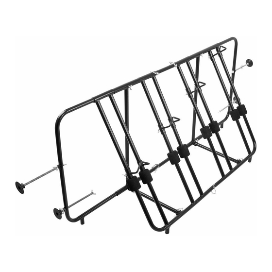
Truck Bed Bike Rack
Instructions for Part # TBBC-4
B
F
Quantity
Part Description
1
F
1
G
1
H
1
I
2
1-888-651-3431
C
H
G
Spacer Bar
Bottom Support Bar
Clip Pin
Plastic Stopper
D
I
Quantity
2
2
9
4
Page 1
Advertisement
Table of Contents

Related Manuals for ELEVATE TBBC-4


Summary of Contents for ELEVATE TBBC-4
- Page 1 Truck Bed Bike Rack Instructions for Part # TBBC-4 General Guidelines • It is the user’s responsibility to read and follow all instructions. • Keep these instructions with the product at all times and review before each use. • It is the responsibility of this product’s owner to furnish the instructions to any person that borrows or pur- chases the product.
- Page 2 Assembly Step 1. Assemble the Left U-Frame (A), Left Main Rack Frame (C), and one Frame Support Bar (E). A. Slide the first section of the Main Rack Frame onto the top bar of the U-Frame until it just fits onto the bar. (The bottom of the U-Frame will have a foot.) B.
- Page 3 (Step 4 cont.) B. The bottom sections of each Main Rack Frame fit together and secure with a Clip Pin. (4B) C. After the sections are in place, tighten the wing nuts on the Frame Support Bars. Step 5. Screw the Plastic Stoppers (I) onto the long wing bolts that are on the U-Frames. The bolt and wing nut may need to be adjusted so that there is room to install the stopper.
- Page 4 Product Warranty and Liability GENERAL PRODUCT WARRANTY: Products purchased from the Authorized Dealer (original place of pur- chase) or Merchant (“Dealer”) will be free of defects in material and workmanship at the time of receipt, and will meet the specifications stated at the place of purchase transaction or online at the Dealer’s website, under nor- mal use and service when correctly installed, operated and maintained.
Need help?
Do you have a question about the TBBC-4 and is the answer not in the manual?
Questions and answers