
Subscribe to Our Youtube Channel
Related Manuals for Spearhead Outfront Flail 130


Summary of Contents for Spearhead Outfront Flail 130
- Page 1 Spearhead Outfront Flail OUTFRONT 130/160 FLAIL Edition 2.0 - April 2016 Part No. 8999090...
- Page 2 VERIFICATION OF WARRANTY REGISTRATION DEALER WARRANTY INFORMATION & REGISTRATION VERIFICATION It is imperative that the selling dealer registers this machine with Spearhead Machinery Limited before delivery to the end user – failure to do so may affect the validity of the machine warranty.
- Page 3 WARRANTY POLICY WARRANTY REGISTRATION All machines must be registered, by the selling dealer with Spearhead Machinery Ltd, before delivery to the end user. On receipt of the goods it is the buyer’s responsibility to check that the Verification of Warranty Registration in the Operator’s Manual has been completed by the selling dealer.
- Page 4 Machinery web site and confirms the registration to the purchaser by completing the confirmation form in the operator’s manual. 2.02. Any fault must be reported to an authorised Spearhead Machinery dealer as soon as it occurs. Continued use of a machine, after a fault has occurred, can result in further component failure for which Spearhead Machinery Ltd cannot be held liable.
- Page 5 Spearhead Outfront Flail CE Declaration of Conformity, Conforming to EU Machinery Directive 2006/42/EC We, Spearhead Machinery Ltd, Green View, Salford Priors, Evesham, Worcestershire, WR11 8SW hereby declare that: Product ……………………………………………..………………………… Product Code ……………………………………………..………………………… Serial No ……………………………………………..……..…………………. Type ……………………………………………..………………………… Manufactured by: Alamo Manufacturing Services (UK) Limited, Station Road, Salford Priors, Evesham, Worcestershire, WR11 8SW Complies with the required provisions of the Machinery Directive 2006/42/EC.
-
Page 6: Table Of Contents
Spearhead Outfront Flail Contents Machine Description...…………………………………………………………………….7 Safety Information………………………………………………………………………..10 Machine Preparation…..………………………………………………………………...14 Fitting to the Tractor.…………………………………………………………………….17 General Operation……………………………………………………………………….21 Maintenance……………………………………………………………………………...26 Troubleshooting………………………………………………………………………….28 Replacement Parts...…………………………………………………………………….29 Disposal…………..…………………………………………………………………….32 Parts……………………………………………………………………………………….33... -
Page 7: Machine Description
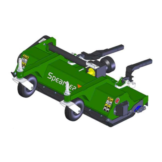
Spearhead Outfront Flail Machine Description Intended usage. The Outfront flail was developed to meet the demands of local authorities for parks and municipal areas. The Outfront is provided in optional cutting widths of 1.3m and 1.6m, variable cutting heights from 8mm to 130mm, a mountable kerb height of 355mm, sealed bearings and pressed scoop flails. - Page 8 Spearhead Outfront Flail Figure 1.2.1 Plan view: Front Left Right Rear Drive guard Drive tube Gearbox PTO Shaft Linkage Arms Skid Front castor wheels Front rubber guard Figure 1.2.2 ISO view: Machine rotation convention The term REVERSE rotation in the following notes indicates the direction of the rotation of the rotor shaft in relation to the tractor wheels, assuming that the tractor is moving in a forward direction.
- Page 9 Mounting availability – please contact your local Spearhead authorised dealership to check for fitment to your tractor unit. A wide range is currently available, and customized linkages for your specific needs are quickly available through our Parts...
-
Page 10: Safety Information
Spearhead Outfront Flail Safety Safety instructions The operator must read, understand and follow all of the Safety instructions. Serious injury or death may occur unless care is taken to follow the warnings and instructions provided. The level of safety is indicated in three levels and the following notation is used throughout this operator instruction book;... - Page 11 Spearhead Outfront Flail DANGER! When using the machine, the operator must make use of personal protection equipment – at the very least eye protection / goggles, hearing protection / noise defenders, and a hard-hat in case of overturning or travelling under low-hanging branches.
- Page 12 Spearhead Outfront Flail Safety Decals Safety decals are located on various points of the machine see figure 2.4.1. They can be identified by the yellow upper panel depicting the hazard, and the lower white panel indicating means of avoidance or precautions to be taken. These decals have no text and it is essential that all operators and personnel associated with the machine fully understand their meanings, which are shown in figure 2.4.2.
- Page 13 Spearhead Outfront Flail Grease point: Warning : Safe Working : Warning : Crushing hazard: Grease every 8 Read instructions Remove ignition Keep nuts Stay clear of key before immediate area hours before use tight working on around machine machine Shaft...
-
Page 14: Machine Preparation
Spearhead Outfront Flail Machine preparation Tractor requirements Before fitting the machine to the tractor ensure that specification of the tractor meets the requirements listed below. A six spline PTO output with of one and three eighths inch diameter shaft; OR a 15 spline PTO output with a one inch diameter shaft is available at the front of the tractor. - Page 15 Spearhead Outfront Flail Lifting the machine The machine will normally be delivered with the linkage arms assembled to the main unit. If this is not the case then specific re-assembly instructions will be provided with the separate link arm kit.
- Page 16 Spearhead Outfront Flail Figure 3.2.2...
-
Page 17: Fitting To The Tractor
– many other fitments are available, please contact your local Spearhead dealership if other versions are required. Wheels to the front and a roller at the rear give height-cut adjustment, allowing the Outfront to cope with many different ground and material conditions. - Page 18 Spearhead Outfront Flail Mounting the Outfront The mounting process is quite straightforward, and with practice and accurate driving, will take only a few moments. Start with the tractor unit engine off, PTO disengaged, and handbrake on. The tractor should be lined up with the back of the Outfront, and about 2 metres behind it. Check your tractor manufacturer’s handbook for any further information regarding safety whilst mounting...
- Page 19 Spearhead Outfront Flail Remove the mounting pins from the Outfront, along with the spacers, ready to receive the linkage arms. Upon first use, the ball-sockets on the end of the linkage arms may need to be manipulated to gain free movement – sometimes there will be paint residue on the ball which is best cleaned off with some rough sandpaper.
- Page 20 Spearhead Outfront Flail Push the mounting pin through its hole firmly, and through the ball socket fully. If the pin is at a slight angle through the holes, a soft-faced mallet may be used to tap the pin home. Ensure that the pin comes all the way through the plates, and it’s lynch pin hole is exposed.
-
Page 21: General Operation
Spearhead Outfront Flail General Operation Lift buffer adjustment The lift buffers allow a range of up and down angles to be achieved with the Outfront, to cater for different terrain and operation conditions. See the figure 5.1.1 for general arrangement of lift buffers. - Page 22 Spearhead Outfront Flail Cut height adjustment The Outfront can cut material at differing heights through adjustment of the roller height, and the castor wheel height. The unit’s front and rear guarding will protect the operator and bystanders from thrown objects, but due to the nature of such guarding - less protection is offered at greater cut heights. See the figure 5.2.1 for general arrangement of cut height adjustment.
- Page 23 Spearhead Outfront Flail DANGER! NEVER, through adjustment, allow the front of the machine to point upwards when in work. NEVER, have the wheels at a greater height than the roller, as this will cause debris to be thrown forward at great speed.
- Page 24 Spearhead Outfront Flail Machine Guarding Machinery guarding must always be kept attached to the machine, and in a good, workable condition. Failure to ensure this, may result in serious injury or even death to either bystanders, or the operator. See the figures 5.4.1 and 5.4.2 below for details on machine guarding.
- Page 25 Spearhead Outfront Flail See section 5.4.3 See section 5.4.4 See section 5.4.6 See section 5.4.2 See section 5.4.5 Figure 5.4.2 5.4.1 Front Guard. Rubber flap with steel mounting guard. 5.4.2 Side Skid. Thick steel. Also carries roller assembly. 5.4.3 PTO Cup.
-
Page 26: Maintenance
Spearhead Outfront Flail Maintenance All maintenance, cleaning and repair operations must be carried out with the Outfront firmly lowered to the ground and detached from the tractor, or with disconnected PTO, engine off and starting key out. Use grease classification DIN 51825 (KP 2 K) - For gearbox use compatible oils – classification ISO VG 220. - Page 27 Spearhead Outfront Flail Belt tensioning Inspect the belts, to ensure there are no scorch marks, nicks, or frayed areas on the belts themselves. If replacement is needed, see section 8.2. To tighten a belt, refer to figure 6.2.1, and perform the following actions;...
-
Page 28: Troubleshooting
Spearhead Outfront Flail Troubleshooting PROBLEM CAUSES REMEDIES Worn, bent or broken flails Replace it / them Machine is not level with the Level the machine Irregular Cut ground Reduce working speed Material blockage due to speed ... -
Page 29: Replacement Parts
Should you require replacement parts, these are detailed in the Outfront parts book accompanying the machine. Alternatively, these are available online to your local Spearhead dealer providing you stipulate the machine serial number. This will identify the specific build of your machine. - Page 30 Spearhead Outfront Flail Figure 8.1.2 – Spearhead ‘Scoop’ flail...
- Page 31 Spearhead Outfront Flail Belt replacement This operation must be carried out with the machine touching the ground, the power take-off disconnected and the starting key out. To replace a belt, refer to figure 8.2.1 and perform the following actions; 8.2.1 Remove the drive belt guarding (not shown in image below) 8.2.2 Slacken the four gearbox mounting bolts...
-
Page 32: Disposal
Spearhead Outfront Flail Disposal If the machine becomes un-serviceable and must be disposed of, the materials that make up the machine must be disposed of separately, in order to stop them becoming a hazard to the local environment. These materials are: a) Steel (cowling, linkage arms, rotor shaft, flails etc.) -
Page 33: Parts
Spearhead Outfront Flail 77.021.02 – 130 COWL ASSY... - Page 34 Spearhead Outfront Flail 77.021.02 – 130 COWL ASSY...
- Page 35 Spearhead Outfront Flail 77.022.02 – 130 ROLLER ASSY...
- Page 36 Spearhead Outfront Flail 77.023.02 – 130 ROTOR ASSY ITEM NO. PART NUMBER. DESCRIPTION. QTY. 48236.04 ROTOR SH ASSY 130 2770364 BOLT 2770574 7770714 FLAIL 48236.15 ANTI-WRAP ASSY 05.625.10 SKT CAPSCREW M12X30 05.624.24 SETSCREW M12X35 05.287.03 SELF-LOCKING NUT M12 BEARING ASSY – FLANGED 03.008.01...
- Page 37 Spearhead Outfront Flail 77.563.09 – 130 DRIVE ASSY...
- Page 38 Spearhead Outfront Flail 77.563.09 – 130 DRIVE ASSY...
- Page 39 Spearhead Outfront Flail 77.563.08 – 160 COWL ASSY...
- Page 40 Spearhead Outfront Flail 77.563.08 – 160 COWL ASSY...
- Page 41 Spearhead Outfront Flail 72.121.22 – 160 ROLLER ASSY...
- Page 42 Spearhead Outfront Flail 77.564.02 – 160 ROTOR ASSY ITEM NO. PART NUMBER. DESCRIPTION. QTY. BEARING ASSY – FLANGED 03.008.01 05.234.01 WASHER 44.5X13X5 PLATED 05.625.10 SKT CAPSCREW M12X30 05.264.24 SETSCREW M12X35 05.287.03 SELF-LOCKING NUT M12 48236.03 ROTOR SHAFT ASSY 160 2770364...
- Page 43 Spearhead Outfront Flail 77.563.07 – 160 DRIVE ASSY...
- Page 44 Spearhead Outfront Flail 77.563.07 – 160 DRIVE ASSY...
- Page 45 Spearhead Outfront Flail 77.560.01 – CASTOR WHEELS ASSY...
- Page 46 Spearhead Outfront Flail 77.567.01 – DECALS - ENGINEERING...
- Page 47 Spearhead Outfront Flail S181013.01 – DECALS - SPEARHEAD...
- Page 48 Spearhead Outfront Flail...
- Page 49 Spearhead Outfront Flail Spearhead Machinery Ltd Green View Salford Priors Evesham Worcestershire WR11 8SW Tel: 01789 491860 Fax: 01789 778683 www.spearheadmachinery.com parts@spearheadmachinery.com...
Need help?
Do you have a question about the Outfront Flail 130 and is the answer not in the manual?
Questions and answers