Table of Contents
Advertisement
Quick Links
Advertisement
Table of Contents

Subscribe to Our Youtube Channel
Related Manuals for SatLab Titan TAL32


Summary of Contents for SatLab Titan TAL32
- Page 1 TAL32 Automatic Level USE R MANU AL info@satlabgps.com | www.titanposition.com...
- Page 2 F O REW ORD Thank you for purchasing the Satlab Automatic Level TAL32. For the best performance of the instrument, please read this user manual carefully and keep them for future reference. I N T RODUC T ION Suitable for construction projects, mines, road works etc., this instrument is equipped with an air compensator.
- Page 3 • Store the instrument in a dry room with consistent temperature. • If the instrument requires repair, make sure that it is checked and repaired by Satlab technicians or by appointed dealers.
-
Page 4: Table Of Contents
C ONTEN T S 1. Important Parts 2. Instrument Operation 2.1 Instrument Settings 2.2 Sight and Focusing 2.3 Measurement 2.3.1 Height Measurement 2.3.2 Height Difference 2.3.3 Stadia Measurement 2.3.4 Angle Measurement 3. Checking and Adjustment 3.1 Circular Bubble 3.2 Line of Sight 4. -
Page 5: Important Parts
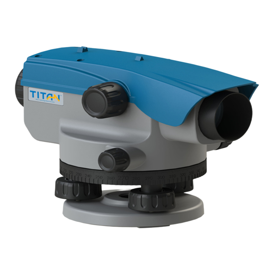
1 . I mpo rta nt Parts This figure shows the parts of the instrument Reflecting Mirror Base Circular Bubble Objective Lens Bubble Adjusting Screw Focusing Knob Endless Drive Eyepiece Horizontal Circle Adjustment Screw Cover Graduation Pointer Peep Sight Footscrews... -
Page 6: Instrument Operation
2 . I ns trume nt Ope rat i on Center Screw Tighten Screw 2. 1 Ins trum ent S e t t i n g Fig. 1 • Extend the tripod legs until the top holder is at eye level. •... -
Page 7: Sight And Focusing
2 . 2 Sig ht an d F ocu s i ng Fig. 3 • Rotate the eyepiece to make the reticle clear (fig. • Target the staff through the peep sight. Then rotate the focusing knob to ensure that the staff image is clear. -
Page 8: Measurement
2. 3 Me as urement 2.3.1 Height Measurement • Use the ruler side of the staff and keep it vertical. • Adjust the eyepiece and focusing knob to make the reticle and staff images clear • Read data as shown in fig. 5, H = 1.403m Fig. -
Page 9: Stadia Measurement
• Then read the staff at point B and obtain the reading as “b” Example: b = 1.224m • The difference a-b is the AB height difference “h” Example: h = a - b = 1.735m - 1.224m = 0.511m Fig. -
Page 10: Angle Measurement
Fig. 7 Difference L = 1.480m -1.328m = 0.152m Distance D = 100 * L = 15.2m 2.3.4 Angle Measurement • Direct instrument to staff A and turn Horizontal Circle to “0” (fig. 8) • Point instrument to staff B •... -
Page 11: Checking And Adjustment
3. C heckin g and Ad j us tme n t Please check the instrument before starting your work. The instrument must be checked and adjusted by a trained person regularly. 3. 1 C ircu lar B ubbl e • Center the bubble of the circular level Fig. -
Page 12: Line Of Sight
• Adjust the rest half of error by using the allen key (fig. 11). • Repeat the above steps until the bubble remains centered when the telescope is pointed at any direction. Fig. 11 3. 2 L in e o f Sig ht •... - Page 13 • Set up the instrument about 1m away from point A. Then read staff A and staff B as “a2” and “b2” (fig. 13). • Then you can get the logical value b2’ = a2 - ΔH , b2’ is the height b2 should be •...
- Page 14 • Rotate the adjusting screw until horizontal hair move to read b2’ Fig. 14...
-
Page 15: Technical Data
4. Tec hnic al D at a Accuracy Standard deviation for 1km double levelling ISO17123-2 1.6mm Telescope Erect Image Magnification: View angle: 1°20’ Valid objective aperture : 38mm Minimum focusing range: < 1.0m Compensator Working range: ±15’ Setting accuracy: ±0.5” Distance Multiplication factor: Measurement... -
Page 16: Packing List
5 . P acking L ist Instrument 1 Piece Manual 1 Piece Carrying Case 1 Piece Allen Key 1 Piece Adjusting Needle 1 Piece Plumb 1 Piece SatLab Geosolution (HK) Limited Unit 335 My Loft, Tuen Mun, New Territories, HongKong titan@satlab.com.se| www.titanposition.com...
Need help?
Do you have a question about the Titan TAL32 and is the answer not in the manual?
Questions and answers