Advertisement
Quick Links
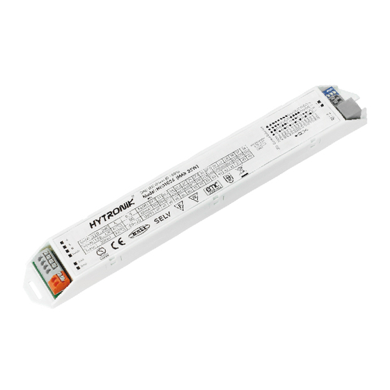
Hex-Drive (With SensorDIM
Constant Current Version - DALI/1-10V/Switch-Dim/SensorDIM
HED1025 / HED1045 / HED1050H / HED1050L / HED1080H
Applications
With both linear and compact versions supporting DALI, 1-10V and Switch-Dim,
or controlled by a versatile range of antenna options, the Hex-Drive range lends
itself to almost any application!
Suitable for LED panels - insulated terminal cover with cable restraint:
Office / Commercial Lighting
Health Care
Classrooms
Low-bay warehouse
Use for retrofit upgrades & new luminaire designs.
Features
with DALI Feedback
1-10V
Switch-Dim with Synchronization
Synchrony
Stand-by Power Consumption
<0.5W
Active PFC Design
>0.93
Configurable Constant Current (CC) Output via Dip-Switch
Analogue Flicker-free Dimming
ANALOGUE
Logarithmic Dimming with Multiple Dimming Inputs:
Intelligent Thermal Management
Thermal Cut-out Protection
Short Circuit Protection
Over-load Protection
Permanent Settings Memory, Protected against Loss of Power
5 Year, 50,000hr Warranty
Output Configuration
HED1025, 1x25W
700mA
675mA
650mA
625mA
600mA
575mA
550mA
525mA
500mA
475mA
450mA
425mA
400mA
375mA
350mA
325mA
1 2 3 4
Warning: Please make sure the correct current is selected before starting the driver!
Hytronik LED Drivers
459
TM
Function)
}
All with Auto-restart
HED1045, 1x45W
1400mA
1200mA
1050mA
900mA
700mA
500mA
1 2 3 4 5
TM
Direct-to-driver occupancy and daylight controls:
For specific features relating to the available sensors,
please refer to the relevant sections of this datasheet
HED1050H, 1x50W
1200mA
1150mA
1100mA
1050mA
1000mA
950mA
900mA
850mA
800mA
750mA
700mA
650mA
600mA
550mA
500mA
1 2 3 4 5
PIR
HF
433/868
HED1050L, 1x50W
600mA
575mA
550mA
525mA
500mA
475mA
450mA
425mA
400mA
375mA
350mA
325mA
300mA
275mA
250mA
225mA
1 2 3 4 5
www.hytronik.com
HED1080H, 1x80W
1650mA
1600mA
1550mA
1500mA
1450mA
1400mA
1350mA
1300mA
1250mA
1200mA
1150mA
1100mA
1050mA
1000mA
950mA
900mA
1 2 3 4 5
Advertisement

Subscribe to Our Youtube Channel
Related Manuals for Hytronik HED1025


Summary of Contents for Hytronik HED1025
- Page 1 Hex-Drive (With SensorDIM Function) Constant Current Version - DALI/1-10V/Switch-Dim/SensorDIM HED1025 / HED1045 / HED1050H / HED1050L / HED1080H Applications With both linear and compact versions supporting DALI, 1-10V and Switch-Dim, or controlled by a versatile range of antenna options, the Hex-Drive range lends...
-
Page 2: Technical Data
79W/ 1100mA /16~72V 80W/ 1150mA /16~70V 80W/ 1200mA /16~66V 80W/ 1250mA /16~64V HED1080H 80W/ 1300mA /16~61V 80W/ 1350mA /16~59V 80W/ 1400mA /16~57V 80W/ 1450mA /16~55V 80W/1500mA /16~53V 80W/ 1550mA /16~51V 80W/ 1600mA /16~50V 80W/ 1650mA /16~48V www.hytronik.com Hytronik LED Drivers... -
Page 3: Wire Preparation
Dimensions and Terminals Model: HED1025 1x25W DIP switch (for LED current selection) LED + LED - Switch-Dim DALI RJ12 (sesor antenna) DALI 254.6 Model: HED1050H 1x50W high current HED1050L 1x50W low current HED1080H 1x80W high current DALI RJ12 sensor antenna... -
Page 4: Wiring Diagrams
1-10V may NOT be used for manual over-ride of DALI Remote control Note: 1. Unused terminals have been omitted for clarity. 2. If connecting an antenna, the DALI and 1-10V inputs are disabled. Please refer to the relevant section in this datasheet for details. www.hytronik.com Hytronik LED Drivers... -
Page 5: Performance Characteristics
0.99 0.98 0.97 0.88 0.96 0.95 0.86 500MA 220V 0.94 850MA 230V 0.84 0.93 1200MA 240V 0.92 0.82 0.91 0.89 0.78 100% 100% LOAD LOAD * Typical Efficiency vs Load * Typical Power Factor vs Load www.hytronik.com Hytronik LED Drivers... - Page 6 0.81 0.95 100% 100% LOAD LOAD * Typical Efficiency vs Load * Typical Power Factor vs Load Dimming Characteristics DALI Dimming Curve Switch-Dim Dimming Curve Light output [%] Light output [%] Time (s) Digital light value www.hytronik.com Hytronik LED Drivers...
- Page 7 Note: In the unlikely event that the LED driver be used with the Switch-Dim or DALI interface prior to using the 1-10V interface, the 1-10V interface may need to be re-set. This is achieved by placing a short circuit across the 1-10V terminals until the light returns to full brightness (approx. 3-5 seconds). www.hytronik.com Hytronik LED Drivers...
- Page 8 Options: Microwave occupancy detection (SAM8/RC11 / SAM11) Daylight Harvest Options: PIR occupancy detection (HIR01 / HIR01/FM / HIR03) HIR01 / HIR02 HIR03 / HIR04 HIR01/FM SAM7 SAM7/FM SAM8/RC11 SAM11 PIR Occupancy Detection Pattern HF Occupancy Detection Pattern www.hytronik.com Hytronik LED Drivers...
- Page 9 RJ12 connector 39.5 Lens PIR Sensor Head Model HIR04 RJ12 connector 40.9 44.5 HF sensorDIM 35.2 Antenna module LED indication Model SAM7 Infrared remote receiver Daylight sensor Cable entry 43.3 Installation hole 52.5 HF sensorDIM Model SAM7/FM www.hytronik.com Hytronik LED Drivers...
- Page 10 Daylight sensor Cable entry 43.3 52.5 Installation hole Daylight Harvest Lens Installation hole PIR Sensor Head Model HIR01 RJ12 connector 39.5 PIR Sensor Head Model HIR01/FM PIR Sensor Head Lens Model HIR03 RJ12 connector 40.9 44.5 www.hytronik.com Hytronik LED Drivers...
- Page 11 Function (HIR04 only) It’s well known that LED lights have a totally different spectrum to natural light. Hytronik uses this principle and comes up with special photocell and sophisticated software algorithm to measure and differentiate natural light from LED light, so that this photocell can ignore the LED light and only respond to the natural light.
- Page 12 People left, the light dims to stand-by level The light switches off automatically after the after the hold-time. stand-by period elapses. Note: end-user can choose either manual override or semi-auto mode for the application. Default mode is manual override. www.hytronik.com Hytronik LED Drivers...
- Page 13 Press buttons in zone “ Daylight threshold” to set daylight sensor at 2Lux / 10Lux / 50Lux / 100Lux / 300Lux / 500Lux / Disable. Note: To set daylight sensor at 100Lux / 300Lux / 500Lux, press “Shift” button first. www.hytronik.com Hytronik LED Drivers...
- Page 14 RC receives signal * This mode can be ended by pressing “reset”, or any button of “scene mode” and successfully. “hold-time”. The sensor settings are changed accordingly. www.hytronik.com Hytronik LED Drivers...
- Page 15 * “0s” means on/off control; “+∞” means bi-level dimming control, the fixture never switches off when daylight sensor is disabled. Stand-by dimming level Press the buttons of “stand-by dimming level” to set the stand-by dimming level at 10% / 20% / 30%. www.hytronik.com Hytronik LED Drivers...
- Page 16 Tri-level Control (Corridor Function) Hytronik builds this function inside the motion sensor to achieve tri-level control, for some areas which require a light change notice before switch-off. The sensor offers 3 levels of light: 100%-->dimmed light (natural light is insufficient) -->off; and 2 periods of selectable waiting time: motion hold-time and stand-by period;...
- Page 17 (master) and receiving unit (slave), the grouping is master slave automatically completed. 16 channels (maximum 16 groups) are available for both the master & slave unit. Use a screwdriver to point the arrow to the same channel on both master and slave. www.hytronik.com Hytronik LED Drivers...
- Page 18 Press button “Start”, button ”100%”, “Disable”, “Shift”, “5min”, “Shift”, “+∞”, “30%”, “Memory”. By pointing to the sensor unit(s) and pressing “Apply”, all settings are passed on the sensor(s). Detection range (valid for master only) Press buttons in zone “Detection range” to set detection range at 100% / 75% / 50% / 10%. www.hytronik.com Hytronik LED Drivers...
- Page 19 Beeper is on /Erase” button to Long press “Learn/Erase” button for 3s to the sensor unit. The beeper quit pairing mode. beeps rapidly for about 5s. All commands received before are erased. The receiver unit (slave) www.hytronik.com Hytronik LED Drivers...
- Page 20 Function (HIR03) It’s well known that LED lights have a totally different spectrum to natural light. Hytronik uses this principle and comes up with special photocell and sophisticated software algorithm to measure and differentiate natural light from LED light, so that this photocell can ignore the LED light and only respond to the natural light.
- Page 21 Press button “Start”, button ”100%”, “Disable”, “Shift”, “5min”, “Shift”, “+∞”, “30%”, “Memory”. By pointing to the sensor unit(s) and pressing “Apply”, all settings are passed on the sensor(s). Detection range Buttons of “detection range” are disabled. www.hytronik.com Hytronik LED Drivers...
- Page 22 The daylight sensor can measure ambient daylight level and ignore the HRC-01 LED light, so as to calculate how much artificial light is needed to maintain the target lux level. Note: the buzzer beeps one time when RC receives signal successfully. www.hytronik.com Hytronik LED Drivers...
- Page 23 Note: “0s” means on/off control; “+∞” means bi-level dimming control and the fixture never switches off. Stand-by dimming level Press the buttons of “stand-by dimming level” to set the stand-by dimming level at 10%/20%/30%/50%. Detection range Buttons of “detection range” are disabled. www.hytronik.com Hytronik LED Drivers...
Need help?
Do you have a question about the HED1025 and is the answer not in the manual?
Questions and answers