Table of Contents
Advertisement
Quick Links
Design and Installation Manual
for Advanced Enviro-Septic® (AES)
Wastewater Systems
For more detailed design and installation information on AES, please contact Infiltrator
Water Technologies at (800) 221-4436 or Presby Environmental, Inc. at (800) 473-5298.
www.infiltratorwater.com • www.presbyeco.com
© Presby Environmental, Inc., Missouri Design & Installation Manual, September 2020 Edition
Missouri
Table of Contents
SEPTEMBER 2020
3
3
4
5
6
6
6
7
8
11
13
17
18
19
22
23
24
Advertisement
Table of Contents

Subscribe to Our Youtube Channel
Related Manuals for Infiltrator Presby Advanced Enviro-Septic


Summary of Contents for Infiltrator Presby Advanced Enviro-Septic
-
Page 1: Table Of Contents
2.7 Venting 2.8 Site Selection 3.0 INSTALLATION 4.0 REJUVENATION AND EXPANSION For more detailed design and installation information on AES, please contact Infiltrator 5.0 OPERATION AND Water Technologies at (800) 221-4436 or Presby Environmental, Inc. at (800) 473-5298. MAINTENANCE 6.0 WARRANTY www.infiltratorwater.com •... - Page 2 The information in this Manual is subject to change without notice. We recommend that you check your state’s page on our website on a regular basis for updated information. Your suggestions and comments are welcome. Please contact us at: Presby Environmental, Inc. 143 Airport Road Whitefield, NH 03598 Phone: 1-800-473-5298 Fax: (603) 837-9864...
-
Page 3: Introduction
• allow DHSS and Presby Environmental (PEI) or Infiltrator Water Technologies (Infiltrator) personnel onto their property to investigate system function. The AES is a combined treatment and dispersal system (CTDS), a system type which is not specifically addressed in 19 CSR 20-3.060 (the Rules). -
Page 4: Background
1.0 INTRODUCTION System Installation Installation shall be undertaken and completed only by an advanced registered onsite wastewater treatment system installer. Variances No variances shall be issued with use of the AES system while approved as an experimental system. 1.2 Background ®... -
Page 5: System Components
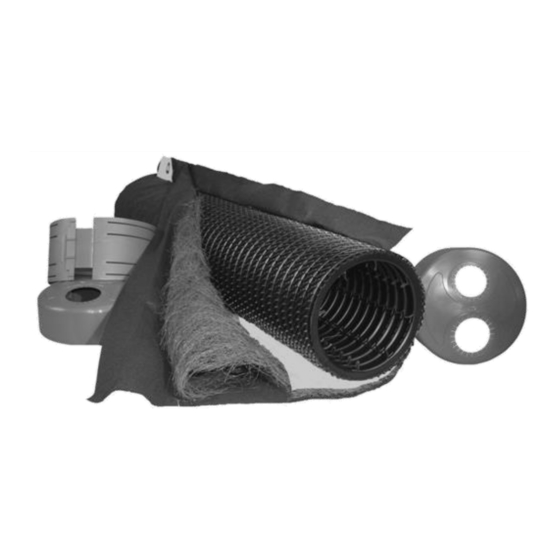
1.0 INTRODUCTION 1.3 System Components AES Pipe: • nominal exterior diameter of 12 in • holding capacity of 5.8 gallons per foot • 10 ft length of AES pipe is flexible enough to bend up to 90° and can be cut to any length •... -
Page 6: System Design
2.0 SYSTEM DESIGN 2.1 System Sizing All residential AES systems require the use of 70 linear feet (lf) of AES pipe per bedroom (br). In non-residential or commercial applications, divide the DDF by 2.14 gal to calculate the minimum amount of AES pipe required. In accordance with the Rules, daily design flow (DDF) is calculated as follows: the minimum flow rate shall be one hundred twenty gallons (120 gals.) per day per bedroom. -
Page 7: Design Examples
2.0 SYSTEM DESIGN system sand extension on the down slope side of the AES system. [Please see sections titled “System Sand Extensions (SSE)” on page 9 and “Elevated Bed Systems” on page 10]. Step #7: Calculate System Sand Extension (SSE): a) Beds sloping 5% or less: SSE is divided in half and placed evenly on each side of AES pipes. -
Page 8: Design Specifications
2.0 SYSTEM DESIGN Design Example #2: Single family residence, 3 bedrooms (360 gpd), SLR = 0.25 gpd/ft², 12% site slope, limiting layer at 14 in. The SLR of 0.25 gpd/ft and the fact that the system will be above grade both require that the system be designed by a licensed professional engineer. - Page 9 2.0 SYSTEM DESIGN Septic Tank The AES system is designed to treat effluent that has received “primary treatment” in a standard septic tank. Septic tanks shall be sized according to the Rules. Pressure Distribution The use of pressure distribution lines in AES systems is prohibited. Pumps may be utilized when necessary only to gain elevation and to feed a distribution box which then distributes effluent by gravity to the AES field.
- Page 10 2.0 SYSTEM DESIGN • If there is no alternative means of disposing of this backwash other than in the system, the system will need to be “oversized.” Calculate the total amount of backwash in gpd, multiply by 2, and add this amount to the daily design flow when determining the field and septic tank sizing.
-
Page 11: System Configurations
2.0 SYSTEM DESIGN 2.5 System Configurations Elevated Bed Systems Elevated beds are designed for sites with soil, depth to groundwater or restrictive feature constraints that do not allow for in-ground bed systems. An elevated bed system is a soil absorption field with any part of the AES system (6 in basal system sand layer and 12 in tall AES pipe rows) is located above original grade. - Page 12 2.0 SYSTEM DESIGN Butterfly Configuration • A “butterfly configuration,” is considered a single bed system with two or more sections extending in opposite directions from the D-box along the contour. • Butterfly configurations are generally used to accommodate bed lengths longer than the maximum row length of 100 ft.
-
Page 13: Pump Systems
2.0 SYSTEM DESIGN Illustration of multiple beds at same elevation: Illustration of multiple beds at different elevations: Angled and Curving Beds Angled and curving beds are used to avoid obstacles and work well around structures, setbacks, and slopes. Multiple curves can be used within a system to accommodate various contours of the site. •... -
Page 14: Venting
2.0 SYSTEM DESIGN • All systems with multiple bed distribution shall use flow equalizers in each D-box outlet with each bed or section limited to a maximum of 15 gpm, due to the flow constraints of the equalizers. Example: pumping to a system using 3 D-box outlets, the maximum delivery rate is (3 x 15) = 45 gpm. - Page 15 2.0 SYSTEM DESIGN Vent Manifolds A vent manifold may be incorporated to connect the ends of a number of sections or rows of AES pipe to a single vent opening. Slope the lines connecting the manifold to the AES pipes to drain condensation. Gravity Systems Vent Location •...
- Page 16 2.0 SYSTEM DESIGN Pump System Vent Locations • A low vent shall be installed into any aspect of the vent manifold on the distal end of the bed (or each section in a multiple bed system). • The vent manifold shall include use of offset adapters.
-
Page 17: Site Selection
2.0 SYSTEM DESIGN Illustration of by-pass venting: 2.8 Site Selection Determining Site Suitability Refer to DHSS regulations and local rules regarding site suitability requirements. Topographic Position Requirement AES systems shall not be located where surface or ground waters will converge, causing surface water flow to become concentrated or restricted within the soil absorption field. - Page 18 2.0 SYSTEM DESIGN • Systems should be located to allow access for septic tank maintenance and to at least one end of all AES rows. • Avoid locating systems in rocky or wooded areas that require additional site work, since this may alter the soil’s ability to accept water.
-
Page 19: Installation
3.0 INSTALLATION 3.1 Installation Requirements Component Handling • Keep mud, grease, oil, etc. away from all components. Avoid dragging pipe through wet or muddy areas. Store pipe on high and dry areas to prevent surface water and soil from entering the pipes or contaminating the fabric prior to installation. - Page 20 3.0 INSTALLATION the topsoil may be left in-place and tilled. Next, use an excavator or backhoe to rake furrows 2 in – 6 in deep into the receiving area. Note: It is not necessary for the soil of the system site to be smooth when the site is prepared. Install System Sand and/or Sand Fill Immediately After Excavation •...
- Page 21 3.0 INSTALLATION Connect Rows Using Raised Connections Raised connections consist of offset adapters, 4 in PVC sewer and drainpipe, and 90° elbows. They enable greater liquid storage capacity and increase the bacterial surfaces being developed. Raised connections extend 2 in to 4 in into pipe and are installed on an angle (as shown in the drawing to the right).
-
Page 22: Rejuvenation And Expansion
4.0 REJUVENATION AND EXPANSION 4.1 Bacteria Rejuvenation and Expansion Why Would System Bacteria Rejuvenation Be Needed? Bacteria rejuvenation is the return of bacteria to an aerobic state. Flooding, improper venting, alteration or improper depth of soil material cover, use of incorrect sand, sudden use changes, introduction of chemicals or medicines, and a variety of other conditions can contribute to converting bacteria in any system from an aerobic to an anaerobic state. -
Page 23: Operation And Maintenance
5.0 OPERATION AND MAINTENANCE 5.1 Operation and Maintenance Proper Use AES systems do not require a maintenance and monitoring agreement, however they do require minimal maintenance as is common for traditional pipe and stone onsite systems, provided the system is not subjected to abuse. -
Page 24: Warranty
6.0 WARRANTY 6.1 PRESBY ENVIRONMENTAL, INC. STANDARD LIMITED WARRANTY (a) The structural integrity of each unit, endcap and other accessory manufactured by Presby Environmental, Inc. (collectively referred to as “Units”), when installed and operated in an onsite wastewater system in accordance with Presby Environmental’s installation instructions, is warranted to the original purchaser (“Holder”) against defective materials and workmanship for one year from the date upon which a septic permit is issued for the septic system containing the Units;...
Need help?
Do you have a question about the Presby Advanced Enviro-Septic and is the answer not in the manual?
Questions and answers