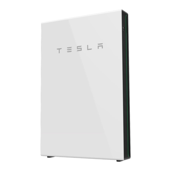
Tesla Powerwall Installation Manual
2 ac with backup gateway
Hide thumbs
Also See for Powerwall:
- Owner's manual (52 pages) ,
- Installation and user manual (33 pages) ,
- Installation manual (30 pages)
Summary of Contents for Tesla Powerwall
- Page 2 FOR PRIVATE HOUSEHOLDS: INFORMATION ON DISPOSAL FOR USERS OF WEEE PRODUCT SPECIFICATIONS ERRORS OR OMISSIONS FOR PROFESSIONAL USERS IN THE EUROPEAN UNION FOR DISPOSAL IN COUNTRIES OUTSIDE OF TESLA TESLA MOTORS THE EUROPEAN UNION POWERWALL...
-
Page 3: Important Safety Instructions
IMPORTANT SAFETY INSTRUCTIONS SYMBOLS USED... -
Page 4: General Information
GENERAL INFORMATION... - Page 8 Figure 1: Powerwall 2 AC and Backup Gateway Dimensions...
- Page 9 Figure 2: Powerwall 2 Identification by Mounting Bracket Height • •...
- Page 10 • • • • • • • • • • • • • • • • • • • • • • • •...
- Page 11 • • • • • • • • • • • • • • • • • •...
- Page 12 • • • • • •...
- Page 13 Figure 3: Mounting Bracket Dimensions Figure 4: Location of Back Cable Entry Port in Relation to Bracket...
- Page 15 Figure 5: Mounting Powerwall on the Bracket...
- Page 16 • •...
- Page 17 • • •...
- Page 18 • •...
- Page 19 Figure 6: Communication Connector Wiring...
- Page 20 Figure 7: Backup Gateway Ground and Communication Connections Figure 8: Powerwall Earth/Ground and Communication Connections with Terminating Resistor...
- Page 22 Figure 9: Powerwall 2 AC Power Harness Connection...
- Page 23 Figure 10: Meter Communication Port Connection on Top of Meter...
- Page 24 Figure 11: Meter Communication Wiring...
- Page 25 Figure 12: Voltage Line Harness with Combined Leads Figure 13: Voltage Tap Port (left) and four CT Ports (right) on Bottom of Meter...
- Page 26 • • • Figure 14: CT Orientation in Relation to Power Flow...
- Page 27 Figure 15: Multiple Conductors Passing Through Single CTs Figure 16: Y-Cables Connecting CTs on the Same Phase...
- Page 29 • • Figure 17: Applying the Rating Label (Left) and Warning Label (Right)
- Page 30 • • • • • • • • • •...
- Page 33 Figure 18: Powerwall 2 Mounting Bracket Dimensions and Space Requirements...
- Page 39 • •...
- Page 40 Figure 19: CT Placement for Whole Home Backup...
- Page 41 • • •...
- Page 42 Figure 20: CT Placement for Partial Home Backup...
- Page 43 • •...
- Page 44 Figure 21: Voltage Tap and CT Placement for Partial Home Backup with Relocated Meter...
- Page 45 • •...
- Page 46 Figure 22: Voltage Tap and CT Placement for Partial Home Backup with Two Meters...
- Page 47 •...
- Page 48 • • • •...
- Page 49 • • • • • • • • • •...
- Page 50 • • • • • • •...
- Page 51 Figure 23: Recommended Interconnection Point for Large Multiple Powerwall Systems Table 1: Impedance Requirements for Multi-Powerwall Systems...
- Page 52 • • • Figure 24: Example 400 A Service with Separate Generation and Load Panels...
- Page 53 Figure 25: Power Flow from Grid and Generation Panel when On-Grid Figure 26: Power Flow from Generation Panel when Off-Grid...
- Page 54 Conduit nipple • • • • • • • • •...
- Page 55 Figure 27: Dimensions for 2-unit and 3-unit Powerwall Stacks...
- Page 58 • •...
- Page 59 • •...
- Page 60 •...
- Page 61 •...
- Page 62 • • • • Figure 28: Connecting Powerwall Communication Ports •...
- Page 65 • • • • • • • • • • • • • • • • • • • • • • • • • • • • • • • • • • • •...
- Page 66 • • • • • • •...
- Page 67 Tesla Motors Netherlands B.V. Tesla, Inc. Atlasstraat 7–9, 5047 RG 3500 Deer Creek Road Tilburg, Netherlands Palo Alto, CA 94304...


Need help?
Do you have a question about the Powerwall and is the answer not in the manual?
Questions and answers