Advertisement
Quick Links
I
N
F
O
R
M
A
T
I
O
N
I
N
F
O
R
M
A
T
I
O
N
I
N
F
O
R
M
A
T
I
O
N
S E R V I C E
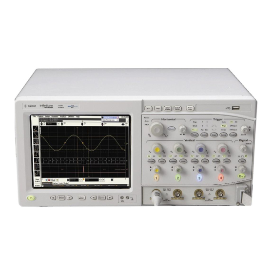
MSO8104A Digitizing Oscilloscope
Serial Numbers: MY00000000-MY46001900
SG00000000-SG46001900
The original scopes motherboard is no longer available for replacement if the
above serial numbers of scopes need a replacement board. This new
replacement motherboard will requires some different cables and other
hardware. This service note is to provide service centers the documentation to
perform the motherboard upgrade.
Parts Required:
P/N
D8104-68700
ADMINISTRATIVE INFORMATION
SERVICE NOTE CLASSIFICATION:
AUTHOR: KO
ADDITIONAL INFORMATION:
© AGILENT TECHNOLOGIES, INC. 2010
PRINTED IN U.S.A.
April 5, 2010
Rev. 17
O
N
L
Y
O
N
L
Y
O
N
L
Y
Description
M880 Motherboard Kit
INFORMATION ONLY
MSO8104A-05A
N O T E
Qty.
1
PRODUCT LINE: 1A
Supersedes:
MSO8104A-05
Page 1 of 14
Advertisement

Related Manuals for Agilent Technologies MSO8104A


Summary of Contents for Agilent Technologies MSO8104A
- Page 1 Parts Required: Description Qty. D8104-68700 M880 Motherboard Kit ADMINISTRATIVE INFORMATION SERVICE NOTE CLASSIFICATION: INFORMATION ONLY AUTHOR: KO PRODUCT LINE: 1A ADDITIONAL INFORMATION: © AGILENT TECHNOLOGIES, INC. 2010 PRINTED IN U.S.A. April 5, 2010 Page 1 of 14 Rev. 17...
- Page 2 Page 2 of 14 MSO8104A-05A Situation: The old motherboard that the units originally shipped with is no longer available. The new replacement motherboard requires new cables and other hardware. Solution/Action: This is the documentation to perform the upgrade M880 Motherboard Upgrade Procedure.
- Page 3 Page 3 of 14 MSO8104A-05A Figure 1 Remove all cables from the PCI cards. Remove all PCI cards from the motherboard. Disconnect all cables from the motherboard. Remove the six 5 mm port lock screws from the rear panel connectors.
- Page 4 Page 4 of 14 MSO8104A-05A Figure 3 Remove the two Torx T20 screws holding the shock mount in place (See Figure 4) You may need to use a Torx key to loosen the screws. Tilt the disk drive assembly forward and lift up to remove.
- Page 5 Page 5 of 14 MSO8104A-05A To disconnect the cable Pry up the retainer slightly at either end of the connector using a small flat-blade screwdriver. Do not force the retainer; it should remain attached to the body of the socket.
- Page 6 Page 6 of 14 MSO8104A-05A Figure 8 Remove the ten Torx T10 screws that secure the front panel cover plate to the front casting. The four screws in circled in are longer be sure to re-assemble correctly. Figure 9 Turn front panel cover plate over and Remove the Touch Screen cable D8104-61604 and...
- Page 7 Page 7 of 14 MSO8104A-05A Figure 10 Turn front panel cover plate back over and re-assemble. When re-assembling, torque the ten Torx T10 screws to 5 in-lb. Remove old Back Light cable D8104-61605 and replace with D8104-61607. See Figure 11...
- Page 8 Page 8 of 14 MSO8104A-05A Figure 12 Route cables though the chassis holes to prepare to reattach the front Panel assembly to the frame. (See figure 12 and 13) Figure 13 and 14 Re-install Front Panel with four Torx T15 screws that secure the chassis sides to the front panel assembly.
- Page 9 Page 9 of 14 MSO8104A-05A Figure 15 Using new Heat Sink and Fan Assembly install fan to Motherboard and Deck. (See Figure 16) Connect fan power cable to fan CPU Fan jack. Torgue fan screws to 5 in-lb. Figure 15 Note: Do not use thermal grease on Heat Sink/Fan assembly.
- Page 10 Page 10 of 14 MSO8104A-05A Figure 16 Re-install Motherboard Assembly into the frame chassis. Install the 3 long Torx T10 screws and two short T10 into the tray holding the motherboard assembly to the frame chassis. (See Figure 17 and 18)
- Page 11 Page 11 of 14 MSO8104A-05A Figure 18 Re-install eight short T20 screws in rear panel attaching deck to the frame chassis. Torgue T20 to 8 in-lb. Re-install three short T10 screws and filler plate to the rear panel. Torgue T10 to 5 in-lb.
- Page 12 Page 12 of 14 MSO8104A-05A Figure 19 Figure 20 Figure 21 Re-connect all other cables to the appropriate sources. Install all ISA slot filler plates (See figure 22)
- Page 13 Page 13 of 14 MSO8104A-05A Figure 22 Tilt the disk drive assembly forward and push down to reinstall. When re-assembling, torque the screws to 18 in-lb. Reattach the following cables: • SATA Cable • Hard Drive Power cable Re-install CDROM Reattach the following cables: •...
- Page 14 Page 14 of 14 MSO8104A-05A Re-dress all cables to their original positions. Making sure they are in the appropriate tie downs and clamps. Re-install top cover and feet and handles.