Table of Contents
Advertisement
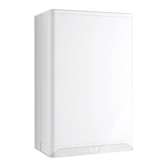
SFT 199 Tankless Water Heater
WARNING: If the information in this manual is not followed exactly, a fi re or
explosion may result causing property damage, personal injury, or loss of life.
Do not store or use gasoline or other fl ammable vapours and liquids or other
combustible materials in the vicinity of this or any other appliance.
WHAT TO DO IF YOU SMELL GAS:
• Do not try to light any appliance.
• Do not touch any electrical switch; do not use any phone in your building.
• Immediately call your gas supplier from a nearby phone. Follow the gas
supplier's instructions.
• If you cannot reach your gas supplier, call the fi re department.
Installation and service must be performed by a qualifi ed installer, service
agency or the gas supplier.
Ce manuel est également disponible en français sur notre site Web, au www.ibcboiler.com/TIPortal.
(Natural Gas or Propane)
www.ibcboiler.com
Advertisement
Table of Contents

Related Manuals for IBC INTERGAS SFT 199


Summary of Contents for IBC INTERGAS SFT 199
- Page 1 SFT 199 Tankless Water Heater (Natural Gas or Propane) WARNING: If the information in this manual is not followed exactly, a fi re or explosion may result causing property damage, personal injury, or loss of life. Do not store or use gasoline or other fl ammable vapours and liquids or other combustible materials in the vicinity of this or any other appliance.
- Page 2 Supplied with the unit - The SFT unit is shipped with an accessory parts kit consisting of the following items: • 1 x Wall Mounting Bracket, 4 x 1¾” bolts - IBC part P-837 • 1 x Condensate trap assembly •...
- Page 3 SFT 199 TANKLESS WATER HEATER SPECIFICATIONS SPECIFICATION SFT 199 Heat Capacity (Input) Natural Gas 28,500-199,000 BTU/H Propane 28,500-199,000 BTU/H Effi ciency Ratings (NG & LP) U.E.F 0.89 Flow Rate (DHW) 35°F (19°C) Temp Rise 10.1 GPM (38 L/m) 45°F (25°C) Temp Rise 7.9 GPM 30 L/m) 67°F (36°C) Temp Rise 5.3 GPM (20 L/m)
- Page 4 SFT 199 TANKLESS WATER HEATER DANGER BURN ° Water temperature over 125°F (52°C) can cause severe burns instantly or death from scalds. ° Children, disabled, and elderly are at highest risk of being scalded. ° See instruction manual before setting temperature at water heater. °...
-
Page 5: Table Of Contents
SFT 199 TANKLESS WATER HEATER CONTENTS 1.0 INSTALLATION ......... . 1-1 1.1 GENERAL. - Page 6 SFT 199 TANKLESS WATER HEATER 3.0 STARTUP & COMMISSIONING ......3-1 3.1 LIGHTING &...
- Page 7 SFT 199 TANKLESS WATER HEATER PRE-INSTALLATION CHECK DANGER Should overheating occur Carefully consider clearances and access, vent travel and termination, gas or the gas supply fails to supply, condensate removal and combustion air supply. shut off, do not turn off or Consider the following: disconnect the electrical •...
- Page 8 SFT 199 TANKLESS WATER HEATER This page is intentionally left blank. INSTALLATION AND OPERATION INSTRUCTIONS...
-
Page 9: Installation
SFT 199 TANKLESS WATER HEATER 1.0 INSTALLATION NOTE Commercial use is allowed 1.1 GENERAL only if the unit is regularly maintained, and the heat exchanger is cleaned at least SFT series gas fi red modulating water heaters are designed to be used for once a year, or more often if domestic (residential) purposes. - Page 10 SFT 199 TANKLESS WATER HEATER Bracket Figure 1b: Dimensions / Connections for SFT Series DESCRIPTION SFT UNIT Exhaust Outlet 3" Schedule 40 Combustion Air 3" Schedule 40 Cold Domestic Water 3/4" Male NPT Connection Hot Domestic Water 3/4" Male NPT Connection Gas Inlet 3/4"...
-
Page 11: Code Requirements
SFT 199 TANKLESS WATER HEATER 1.2 CODE REQUIREMENTS WARNINGS - Keep the unit area free The SFT water heaters are certifi ed under CSA 4.3 / ANSI Z21.10.3. and clear of combustible materials, gasoline, and The installation must conform to the requirements of the authority having other fl... -
Page 12: Mobile Home Installations
SFT 199 TANKLESS WATER HEATER DISTANCE FROM RECOMMENDED DISTANCE DANGER SURFACE COMBUSTIBLE FOR INSTALLATION AND SURFACES SERVICE Do not common vent the SFT series water heaters with Front 2" 24" any other existing or new Rear 0" 0" appliance. 6" (labels may be diffi cult to read with Left Side 1.5"... -
Page 13: Exhaust Venting And Air Intake
When you plan the installation, ensure that you consider appropriate venting drainage, and combustion materials, travel and termination decisions. In particular, you should manage the air systems for all IBC units impact of the steam plume typically at the exhaust terminal of a condensing unit. must comply with applicable Generally, intake and exhaust pipes terminate at a rooftop or sterile wall location. -
Page 14: Applications
SFT 199 TANKLESS WATER HEATER Removal of an existing appliance For each appliance remaining connected to the common venting system, you must follow the steps below. Before you begin, ensure that any other appliances connected to the common venting system are not in operation. •... -
Page 15: Vent Travel
Manufacturers of stainless steel Type BH venting systems must submit their approved transition fi tting to IBC for evaluation and written approval. 1.4.3 Vent Travel PVC, CPVC or PPs (Rigid Single Wall) piping is the standard venting option that enables units to be vented up to 120 equivalent feet from the vent termination using 3". - Page 16 SFT 199 TANKLESS WATER HEATER Follow all installation instructions supplied by the pipe and fi tting manufacturer. Prior to assembly, ensure all venting components are clean of burrs/debris. Take care to avoid ingestion into the fan of PVC debris left in the combustion air piping.
-
Page 17: Venting Passage Through Ceiling And Floor
IBC • Pipe clearances - no IBC requirements, but best practice allows a minimum 1/4" recommended minimum gap around the pipe to prevent binding and expansion noise. Follow local codes. requirements, and may •... - Page 18 SFT 199 TANKLESS WATER HEATER Figure 6: Vertical Concentric Termination - Two Kits Figure 7: Vertical Concentric Termination - Single Kit DIRECT VENT CONCENTRIC ROOF TOP TERMINATION Roof Top Concentric Termination kits are approved for use with this unit. For vertical roof top concentric terminations, you must follow the installation instructions supplied with the venting material manufacturer.
-
Page 19: Sidewall Vent Termination
SFT 199 TANKLESS WATER HEATER 1.4.6 Sidewall Vent Termination WARNINGS Direct Vent - Two Pipe - You must maintain at least the minimum separation of Sidewall direct vent applications must be vented as follows: exhaust vent termination • Both the inlet and exhaust terminations should normally be located on the from unit’s intake air as same plane (side) of the building. - Page 20 SFT 199 TANKLESS WATER HEATER Approved Side Wall Termination Kits are listed below: (Alternative vent termination kits must be submitted to IBC for approval prior to installation.) • Ipex - #196984 – 2" PVC low profi le termination kit •...
- Page 21 Figure 14: Prohibited installation manufacturer. Approved concentric side wall termination kits are listed below: (Alternative vent termination kits must be submitted to IBC for approval prior to installation.) • Centrotherm – Innofl ue #ICWT242 (2” termination) + ICTC0224 (2” transition to 2 pipe) •...
- Page 22 SFT 199 TANKLESS WATER HEATER Vent terminal clearance minimums are as follows: WARNINGS CANADIAN US INSTALLATIONS - In addition to preventing INSTALLATIONS ingestion of chemical A= Clearance above grade, 12 in (30 cm) 12 in (30 cm) contaminants, care must veranda, porch, deck, or be taken to ensure air balcony...
-
Page 23: Direct Vent" Combustion Air Intake Unit's Piping
SFT 199 TANKLESS WATER HEATER INSIDE CORNER DETAIL FIXED CLOSED OPERABLE FIXED CLOSED OPERABLE V VENT TERMINAL X AIR SUPPLY INLET AREA WHERE TERMINAL IS NOT PERMITTED Figure 15: Vent Terminal Clearance 1.4.7 “Direct Vent” Combustion Air Intake Unit’s Piping The unit must always be installed as a Direct Vent venting system with the combustion air piped directly from the outdoors to the unit’s combustion air connection. -
Page 24: Indoor Air" 1.4.8 "Indoor Air" Combustion Air Intake
SFT 199 TANKLESS WATER HEATER Intake Pipe Sizing For 3" Flexible PPs, you can use up to 35 actual lineal feet in a nominally vertical orientation (>45°). The equivalent length of 3" Flexible PPs must be calculated using a multiple of 1.4:1, e.g. 35' x 1.4 = 49' equivalent. The balance of the venting allowance is still available for use with rigid PPs piping material. -
Page 25: Condensate Removal
WARNING Fill the trap with water before IBC’s specifi ed vent confi guration promotes the safe drainage of moisture fi rst fi ring the unit to prevent from the unit and exhaust venting without fl owing liquids back through the heat exhaust fumes from entering exchanger. -
Page 26: Cleaning The Condensate Trap
SFT 199 TANKLESS WATER HEATER 1.5.3 Cleaning the Condensate Trap DANGER Turn off the power to the water heater and allow it to cool down. The water in the condensate Twist the condensate trap cup toward the left and lower the trap cup. neutralizer can cause severe burns to the skin. -
Page 27: Water Piping - Space Heating
SFT 199 TANKLESS WATER HEATER Figure 19: Condensate neutralization tank 1.6 WATER PIPING - SPACE HEATING The SFT series water heaters are approved for use as a space heating appliance. All piping system components must be approved for use in a domestic water piping system. -
Page 28: Domestic Hot Water System
SFT 199 TANKLESS WATER HEATER 1.7 DOMESTIC HOT WATER SYSTEM DANGER BURN ° Water temperature over 125°F (52°C) can cause severe burns instantly or death from scalds. ° Children, disabled, and elderly are at highest risk of being scalded. ° See instruction manual before setting temperature at water heater. °... - Page 29 SFT 199 TANKLESS WATER HEATER 1.7.1 Domestic Hot Water System The SFT series tankless water heaters have an independent piping circuit for effi ciently generating Domestic Hot Water. When a faucet is opened to draw hot water, water fl ow is detected with a fl ow sensor and the unit fi res up to begin generating domestic hot water.
-
Page 30: Domestic Hot Water Piping
SFT 199 TANKLESS WATER HEATER 1.7.2 Domestic Hot Water Piping WARNING The domestic water piping connections are located at the bottom of the unit, see - Bacteria growth can develop Figure 23 - Gas Piping. The connections are " male NPT threads. The cold water ¾... - Page 31 SFT 199 TANKLESS WATER HEATER CAUTION The fi eld supplied thermostatic mixing valve may be installed on the domestic hot water piping connections at the unit or at the outlet of a domestic hot water storage tank. DOMESTIC HOT WATER DELIVERY @ 67°F / 37.2°C temperature rise...
-
Page 32: Gas Piping
SFT 199 TANKLESS WATER HEATER 1.8 GAS PIPING WARNING This water heater model can The unit must have an inlet gas pressure of at least 5.0" w.c. for natural gas and burn either natural gas or propane. For either fuel, the inlet pressure shall be no greater than 14.0" w.c. propane. -
Page 33: Electrical Connections
National Electrical NOTE Code, ANSI/NFPA 70, and/or the Canadian Electrical Code Part I, CSA C22.1, Electrical Code. - The IBC unit (like any modern appliance that contains 1.9.1 120VAC Line Voltage Hook-up electronic equipment), must have a “clean”... - Page 34 SFT 199 TANKLESS WATER HEATER 95,0 mm SFT series Schematic Wiring Diagram Flue Sensor 3 way valve Ignition Power Plug 120V Heat ex. Sensor DHW Hot NTC DHW Cold NTC DHW Flow Sensor Gasvalve Blower Motor Control Module SFT series Ladder Wiring Diagram Power Plug Blower 3 Way Valve...
-
Page 35: Unit System Operation
SFT 199 TANKLESS WATER HEATER 2.0 UNIT SYSTEM OPERATION 2.1 GENERAL The SFT units can be used as a tankless water heater, with or without a storage tank. The unit is equipped with an electronic unit controller that ignites the burner and continuously monitors the fl ame throughout each call for heat. -
Page 36: Control
SFT 199 TANKLESS WATER HEATER 2.2 CONTROL ICON FUNCTION Numerical Display Main Display Plus & Minus Temperature Adjustment Flame Burner ON Indicator Power ON Indicator Faucet DHW Indicator Wrench Service / Reset Return Arrow Enter / Save Numerical Display Service Display Table 8: Controller Indicators and Touch Pad 2.3 INSTALLER INTERFACE 2.3.1 Turning Appliance ON/OFF... - Page 37 SFT 199 TANKLESS WATER HEATER 2.3.2 Programming Mode NOTE There are two parameters available in the User Setup Menu. The domestic hot water Adjusting the Domestic Hot Water Temperature thermostat is adjusted to its lowest temperature position To adjust the DHW: when shipped from the 1.
-
Page 38: Tankless Domestic Hot Water Modes
SFT 199 TANKLESS WATER HEATER 2.4 TANKLESS DOMESTIC HOT WATER MODES 2.4.1 Tankless Domestic Hot Water - Standard and ECO Comfort Modes Standard Mode (OFF): The water heater’s heat exchanger will not maintain its domestic hot water temperature between demands for hot water. Comfort Mode (ON): The water heater’s heat exchanger is maintained at the DHW temperature. -
Page 39: Adding Domestic Hot Water Storage
SFT 199 TANKLESS WATER HEATER 2.5 ADDING DOMESTIC HOT WATER STORAGE 2.5.1 Tankless Domestic Hot Water with a Storage Tank The SFT series unit has the ability to connect a domestic hot water storage tank to the unit to provide larger volumes of domestic hot water during peak demands. The storage tank is piped to the unit’s domestic hot and cold water piping connections. -
Page 40: Accessing The Information Menu
5 seconds a hard lock-out condition the Fan Pre-purge , Inter-purge and Post-purge burner will not operate. IBC is not responsible for damages Trial for Ignition and Flame Proving to the unit, and/or related Heating –... - Page 41 SFT 199 TANKLESS WATER HEATER See below for a description of the codes: Table 10: Information Menu Note that display parameters may differ depending on the confi guration. Where there is no DHW sensor, the display reading can be ignored. STARTUP AND COMMISSIONING...
- Page 42 SFT 199 TANKLESS WATER HEATER SFT 199 TANKLESS WATER HEATER This page is intentionally left blank. INSTALLATION AND OPERATION INSTRUCTIONS INSTALLATION AND OPERATION INSTRUCTIONS...
-
Page 43: Startup & Commissioning
SFT 199 TANKLESS WATER HEATER 3.0 STARTUP & COMMISSIONING 3.1 LIGHTING & SHUTTING DOWN THE UNIT STARTUP AND COMMISSIONING... -
Page 44: Prior To Start-Up
SFT 199 TANKLESS WATER HEATER SFT 199 TANKLESS WATER HEATER 3.2 PRIOR TO START-UP DANGERS - Fill trap with water before 3.2.1 Pre-Ignition Checks unit is fi rst fi red to prevent exhaust fumes from entering Fill the condensation trap. Ensure the venting system is complete and seal- room. - Page 45 Static manometer reading should be ideally 7” w.c., appliance, a conversion kit for natural gas and 11” w.c. for propane. Minimum and maximum static must be ordered from IBC pressure must be between 5” and 14” w.c. Monitor pressure throughout the and the gas valve adjusted commissioning procedure.
-
Page 46: Fuel Conversion
SFT 199 TANKLESS WATER HEATER 3.4 FUEL CONVERSION DANGER Operating any IBC appliance The SFT series modulating water heater is factory fi re-tested to operate with using a fuel other than the natural gas. The rating plate is marked to indicate which fuel the particular unit fuel listed on its rating plate is has been set up with. -
Page 47: Gaining Access To Combustion Chamber, Burner Removal Instructions
SFT 199 TANKLESS WATER HEATER WARNING Each SFT series unit is equipped with a back fl ow valve installed at the outlet of the fan. Inspect the back fl ow fl apper annually. Figure 29: Back Flow Valve Figure 30: Blower and Gas Valve Assembly 3.4.1 Gaining access to combustion chamber, burner removal instructions DISASSEMBLY... - Page 48 SFT 199 TANKLESS WATER HEATER SFT 199 TANKLESS WATER HEATER When removing the heat exchanger cover in step 6, be careful CAUTION: not to damage the burner and refractory material located on the opposite side of the heat exchanger cover. Use caution when handling refractory materials. See Caution on page 4-2.
-
Page 49: Maintenance
SFT 199 TANKLESS WATER HEATER 4.0 MAINTENANCE WARNINGS 4.1 WATER HEATER MAINTENANCE - Fill the trap with water before the unit is fi rst fi red to prevent exhaust fumes from entering the room. Never 4.1.1 General Care operate the unit unless the •... -
Page 50: Heat Exchanger
SFT 199 TANKLESS WATER HEATER 4.1.6 Heat Exchanger CAUTION During annual inspection (with the heat exchanger cover removed), examine The heat exchanger has a small the heat exchanger for signs of contamination and clean if necessary. In areas amount of combustion chamber of poor gas quality or contaminated combustion air, there may be a build-up of insulation (refractory) that black plaque (typically sulfur). -
Page 51: Domestic Hot Water System
SFT 199 TANKLESS WATER HEATER 4.1.11 Domestic Hot Water System CAUTION Quality of the domestic cold water is very important to the longevity of the unit. Before testing the relief valve, The recommended pH of the domestic water is between 6.5 and 8.5. The internal make certain the discharge domestic water heat exchanger tubing and the fl ow sensor is subject to fouling if pipe is properly connected to... - Page 52 SFT 199 TANKLESS WATER HEATER Connect the electrical plug to the fan. Restore the gas supply to the unit, and test the gas valve inlet for gas leaks. Restore the power to the unit, and create a call for hot water. Check for leaks at the gas valve outlet and the connection between the fan and the burner housing.
-
Page 53: Troubleshooting
SFT 199 TANKLESS WATER HEATER 5.0 TROUBLESHOOTING The troubleshooting section is divided into four sections: NOTE 5.1 Preliminary Checks This appliance is equipped 5.2 Electronic Components with a blocked vent shut-off 5.3 Warnings and Faults system that closes the gas supply when it detects an 5.4 Other Faults irregular venting condition. -
Page 54: Electronic Components
SFT 199 TANKLESS WATER HEATER 5.2 ELECTRONIC COMPONENTS This section details the method for troubleshooting the non-standard electronic components on the unit. 5.2.1 Temperature Sensors The resistance of the temperature sensors varies inversely with temperature. To test, measure the temperature of the sensed environment and compare with the value derived from the measurement of the resistance (obtained by connecting a good quality test meter capable of measuring up to 5,000 KΩ... -
Page 55: Fan/Blower
SFT 199 TANKLESS WATER HEATER 5.2.2 Fan/Blower Control and power to the fan is provided via a single wiring harness to the controller. 5.2.3 Flue Gas Temperature Sensor This sensor ensures that the unit shuts down safely if the heat exchanger or the venting system becomes blocked. -
Page 56: Warnings And Faults
SFT 199 TANKLESS WATER HEATER 5.3 WARNINGS AND FAULTS 5.3.1 Warning Codes During operation the controller can detect unusual situations and can take action to avoid damage to the heat exchanger or other unsafe operations. During these situations, the controller limits the temperature and power output of the burner, or temporarily disables operation entirely. - Page 57 SFT 199 TANKLESS WATER HEATER F008 Incorrect fan speed • Check the fan cable. • Check and/or replace the fan. • Replace the burner controller. F009 Internal fault in burner • Replace the burner controller. controller. F010, F011 Sensor fault S0. •...
-
Page 58: Other Faults
SFT 199 TANKLESS WATER HEATER 5.4 OTHER FAULTS 5.4.1 No heat (central heating) fault codes POSSIBLE ANALYSIS POSSIBLE SOLUTION CAUSES The power LED is not → Yes • Check the power supply. shown. • Check the fuse (see Electrical schematic). •... -
Page 59: Burner Ignites Loudly
SFT 199 TANKLESS WATER HEATER 5.4.4 Burner ignites loudly POSSIBLE CAUSES ANALYSIS SOLUTION Inlet pressure is too high. → Yes The home pressure regulator may be defective. In that case, contact the energy company. ↓No Ignition distance is incorrect. → Yes Replace the ignitor including the ignition cable. - Page 60 SFT 199 TANKLESS WATER HEATER This page is intentionally left blank. INSTALLATION AND OPERATION INSTRUCTIONS...
-
Page 61: Diagrams
SFT 199 TANKLESS WATER HEATER 6.0 DIAGRAMS 6.1 - PARTS DIAGRAMS 6.2 - WIRING DIAGRAMS DIAGRAMS... - Page 62 SFT 199 TANKLESS WATER HEATER 6.1 PARTS DIAGRAMS SFT Series water heater - Parts assembly Diagram 6.1-1: Unit assembly parts INSTALLATION AND OPERATION INSTRUCTIONS...
- Page 63 SFT 199 TANKLESS WATER HEATER BOM ID Part Description Part # Replacement Kit Numbers 180-204 P-810 Flue exhaust fi tting Combustion air intake fi tting and screen 180-203 P-809 Rear fl ue duct 180-239 P-813 150-312 *Flue / Heat exchanger gasket *Flue Pipe Outlet Gasket 150-313 Flue gas temperature sensor...
- Page 64 SFT 199 TANKLESS WATER HEATER BOM ID Part Description Part # Replacement Numbers *O-ring and orifi ce 150-175 included with conversion kits Orifi ce - Natural Gas - #660 180-173 P-803 Orifi ce- Propane - #535 180-174 P-802 Alternative low calorfi c Natural Gas Orifi ce - # 725 180-108 P-846 Gas valve...
- Page 65 SFT 199 TANKLESS WATER HEATER 6.2 WIRING DIAGRAMS 95,0 mm SFT series Schematic Wiring Diagram Flue Sensor 3 way valve Ignition Power Plug 120V Heat ex. Sensor DHW Hot NTC DHW Cold NTC DHW Flow Sensor Gasvalve Blower Motor Control Module SFT series Ladder Wiring Diagram Power Plug Blower...
-
Page 66: Installation & Commissioning Report
INSTALLATION & COMMISSIONING REPORT Water Heater Details: Model Number _____________________ Serial Number ______________________________________________ Date of Installation ______________ Address of installation __________________________________________ _____________________________________________________________________________________________ User contact information _______________________________________________________________________ Installer Information Company ___________________________________________________________________ Address ______________________________________________________________________________________ Phone/Fax/E mail ____________________________________________________________________________ Fuel Natural Gas Propane Gas Supply Pressure (high fire) _______ Inches w.c. Measured Rate of Input (high fire) ____________ Btu/hr Installation instructions have been followed and completed (Section 1 of Installation and Operating Instructions). -
Page 67: Service Record
SERVICE RECORD DATE LICENSED CONTRACTOR DESCRIPTION OF WORK DONE... -
Page 68: Notes
NOTES... -
Page 69: Revision History
REVISION HISTORY DECEMBER 2018 Initial release FEBRUARY 2019 Miscellaneous minor revisions made. MARCH 2019 Dimension drawings updated and minor revisions. APRIL 2019 References to SFT as being designed for domestic purposes only and need for replacement of heat exchanger gasket during maintenance. - Page 70 IBC Technologies USA Inc. 8015 North Fraser Way 1702 Taylors Lane Burnaby, BC Cinnaminson, NJ 08077 Canada V5J 5M8 Toll Free: 1.844.432.8422 Tel: 604.877.0277 Tel: 856.887.0544 Fax: 604.877.0295 Fax: 856.735.5584 www.ibcboiler.com www.usa.ibcboiler.com 120-232E-R5 88996405 NOVEMBER 2019 © IBC Technologies Inc. 2019...
Need help?
Do you have a question about the INTERGAS SFT 199 and is the answer not in the manual?
Questions and answers