Advertisement
Quick Links
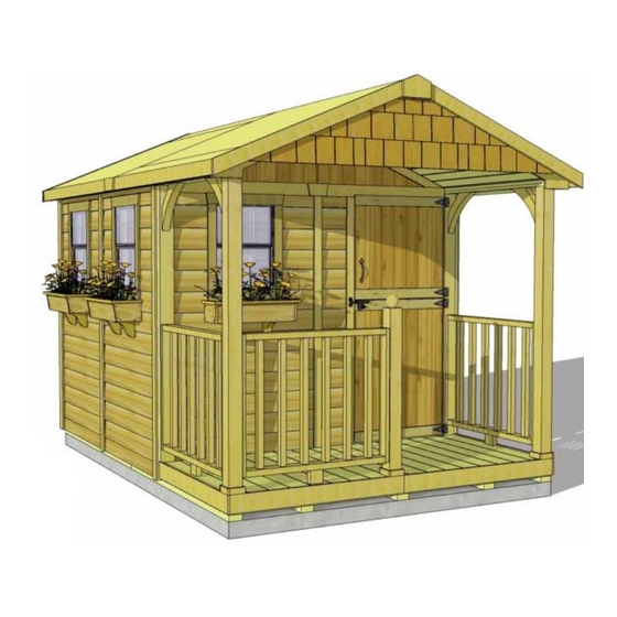
Roof Area: 113 sqft
Thank you for purchasing
an 8x12 Santa Rosa Garden
Shed from Outdoor Living
Today. Please take the time
to identify all the parts prior
to assembly.
Safety Points and Other onsiderations:
Our products are built for use based
on proper installation and normal
residential use, on level ground. Please
follow the instruction manual when
building your Santa Rosa and retain
the manual for future maintenance
purposes.
Some of the safety and usage measures you may wish to consider include:
-snow load ratings vary by geographical location. If heavy or wet snowfall occurs, it is advisable to sweep the
snow off the roof(s).
-if the product is elevated, any structural and building code requirements are solely the customer's
responsibility, and should be abided by.
-in high or gusty wind conditions it is advisable to keep the structure securely grounded.
-have a regular maintenance plan to ensure screws, doors, windows and parts are tight.
Customer agrees to hold Outdoor Living Today Partnership and any Authorized Dealers free
of any liability for improper installation, maintenance and repair.
In the event of a missing or broken piece, simply call the Outdoor Living Today Customer
Support Line @ 1-888-658-1658 within 30 days of the delivery of your purchase. It is our
commitment to you to courier replacement parts, free of charge, within 10 business days of this
notification. Replacement parts will not be provided free of charge after the 30 day grace period.
Toll Free 1-888-658-1658
8x12 Santa Rosa
Assembly Manual
with Plywood Roof
www.outdoorlivingtoday.com
Page 1
Version #2.0
September 1st, 2020
sales@outdoorlivingtoday.com
Advertisement

Related Manuals for OLT 8x12 Santa Rosa


Summary of Contents for OLT 8x12 Santa Rosa
- Page 1 Plywood Roof Version #2.0 September 1st, 2020 Roof Area: 113 sqft Thank you for purchasing an 8x12 Santa Rosa Garden Shed from Outdoor Living Today. Please take the time to identify all the parts prior to assembly. Safety Points and Other onsiderations:...
- Page 2 Thank you for purchasing our 8x12 Santa Rosa Garden Shed. Please take the time to identify all the parts prior to assembly. A. Floor Section Parts List - Pages 2 and 3 Steps Floors 1 - 11 3 - 45 7/16” x 75” - Floor Joist Frames - Large 3 - 45 7/16”...
- Page 3 Parts list continued... Continued Parts List - Page 3 67 - 70 1 - 1/2” x 2 1/2” x 77 1/2” - Rear Wall Seam Trim 2 - 1/2” x 2 1/2” x 72” - Porch & Door Trims 2 - 1/2’ x 2 1/2” x 45 7/8” - Porch Roof Seam Trims 1 - Small Porch Detail Plate 3 - Facia Detail Plates Steps...
- Page 4 8x12 SANTA ROSA - PLYWOOD ROOF HARDWARE SHEET Hardware Kit (Provided) 3/4” x 23 x 260 2 1/2” Black Headed x 235 2” 1 1/2” Shingle x 35 2” Black Headed 1 1/2” x 465 Finishing 1 1/4” x 315 3/4”...
- Page 5 What Can I Do Before My Shed Arrives? Before starting your project become familiar with this assembly manual and determine if you can complete the project yourself or will require a professional contractor. Please note that certain counties and municipalities require building permits prior to installation. We recommend to all consumers that they check with their local county/municipality for these specifics prior to purchasing any of our products since this is your sole responsibility.
- Page 6 Exploded view of all parts necessary to complete A. Floor Section Floor Section. Identify all parts prior to starting. Note: Floor Footprint is 136 1/2” deep x 96” wide. Floor Plywood Floor Joists (7) Large (2) Floor Joist Frames Large (3) Plywood Floor Small (2) Floor Joist...
- Page 7 Attach each large and small floor joist frames together with 6 - 2 1/2” screws per section. Lay out Floor Joist Frames as illustrated. Hardware (Step 4) There are 3 larger and 3 smaller Frame Sections. S1 - 2 1/2” Screws The Footprint for the floor when attached together x 18 total will be 136 1/2”...
- Page 8 With Floor Runners Note: The floor will be flipped over and attached, carefully flip floor runners will sit on your foundation. the floor over and place It is important to note that having a your foundation. level foundation is critical. Choosing a Caution: you will need 2 foundation will vary between regions.
- Page 9 Exploded view of all parts necessary to complete the B. Wall Section Wall Section. Identify all parts prior to starting. Rear Gable Filler Narrow Wall Shingles (2) Middle Gable Panel (12” wide) Front Wall Trim/Supports (2) Walls (2) Rear Gable Left &...
- Page 10 Bottom Wall Plate Parts (Steps 13) Starting with All Solid Wall Panels, carefully lay panel face down. Bottom Wall Plates Position and attach Bottom Wall Plates to bottom of wall studs of each wall (1 5/8” x 2 1/2” x 45 1/2”) x 4 panel with 3 - 2 1/2”...
- Page 11 Do Not Attach Walls To Floor Until Step 24. Position rear corner wall into place and attach together with 3 - 2 1/2” screws. Screw at the top, middle and bottom of 2x3 stud. Start positioning adjacent wall panels and fastening togeth- Optional: Caulking seams will help Hardware (Steps 15 - 18) prevent moisture from entering.
- Page 12 Narrow Wall Parts (Steps 18) To complete walls, attach the Narrow Porch Wall to Narrow Porch Wall x 1 front wall panel. Note: the narrow wall is only 73” high. Attach wall stud to adjoining wall with 3 - 2 1/2” screws. Door Header positioned with Dado to front...
- Page 13 Exploded View of Porch Rail Section Complete the 2 Porch Rail Sections, Front Porch Extension following steps A through E. Corner PreDrill! Brackets 2 - 2” screws Front Porch Extension Hand Rail Section Long Long Porch Porch Post Post Attach Front Porch Extension (3/4”...
- Page 14 Flush PreDrill! 2 - 2 1/2” Screws Thick edge of Wall Trim/Support 2 - 2 1/2” Screws PreDrill! Flush Deck Board Attach Outer Deck Board (1” x 5 1/2” x 44”) to the Wall Trim/Support with 2 - 2 1/2” Screws fastened horizontally as shown above. Ensure Deck Board is flush with the thick edge of the Wall Trim/Support.
- Page 15 3 - 2” screws 3 - 2” screws PreDrill! PreDrill! Corner Bracket centered Corner Bracket in line with on Long Porch Post. opposite side Bracket. This will be off center on the Front Wall Trim/Support. Position Corner Bracket centered on the Long Porch Post as shown. Position opposite side Corner Bracket in line with first.
- Page 16 Flush with Side Wall Framing View from below Flush with Floor Framing Thin part of Wall Trim/Support covers siding on Front Wall. With the Porch Rail Sections complete, attach to the deck area as shown. Outer Deck Board will be positioned flush with the Floor Frame in the front corner.
- Page 17 Lay all Deck Boards down evenly spaced prior to attaching. Attach remaining 15 Deck PreDrill! Boards using 4 - 2” Screws per piece. Equally space all deck boards before attaching. Ensure screws enter the floor joists beneath deck boards. Pre- drill for screws at the ends of the deck boards.
- Page 18 Wall Plate Angle screws into perimeter Floor Joists. Optional - Caulking seams will 32” wide help prevent moisture from entering your shed. Confirm 32” Wide Door Opening at Top and Bottom. Caulking not included in kit. Hardware (Steps 24) When all walls are attached together, check alignment with the floor. Bottom S1 - 2 1/2”...
- Page 19 4 - 2” Screws PreDrill! 1 - 2” Screw 3 - 1 1/4” Screws Attach the 4 Side Top Plates. The side top plates are angle cut down the length. Once again, position top plate on wall plate so it is flush with inside of wall plate.
- Page 20 Attach Wall Trim/Supports to wall with 3 - 2 1/2” screws per side. Try to conceal screws if possible. Hardware (Steps 28) S1 - 2 1/2” Screws x 6 total At the doorway of your shed there will be a small gap between the deck boards and floor plywood.
- Page 21 See Step 57 for explanation of exposure line. From the outside, slide in a Rear Gable Wall Filler Shingle to cover gable seam. Nail down above the exposure line with 2 - 1 1/2” Shingle Nails. Complete by attaching the short 7 1/2” top Filler Shingle with 2 - 1 1/2”...
- Page 22 Gable Notch Siding is flush with framing Locate both Middle Gable Walls and attach together as per Step 30. Parts (Steps 33) Hardware (Steps 33) Middle Gable Walls x2 S1 - 2 1/2” Screws x 3 total Position the Middle Gable Wall on top of front top plate. Middle gable has cedar siding on the front that is cut flush with gable framing.
- Page 23 C. & D. Rafter and Roof Section Exploded view of all parts necessary to complete the Roof Section. Identify all parts prior to starting. Small Roof Large Roof Panels (4) Panels (4) Ridge Boards (4) 2 - 84” long 2 - 52 1/2” long Roof Gussets (2) Rafter...
- Page 24 Ridge Board Locate 9 - Rafters, 2 - Soffits & complet- 2 1/2” Screws ed Ridge Board. Lay out on level ground as into Doubled shown to the right. Double up Rafters as illus- up Rafters trated. Screw doubled up Rafters together with 3 - 2 1/2”...
- Page 25 Soffit Carefully lift 1 completed Rafter Section up (make sure Soffit is facing down) and place on gable framing. Gable Notch Soffit should sit approx. 1/8” away from wall panel. End Rafter will sit flush with end of wall. Slide Rafter Section up on gable framing until bottom of Ridge Board slips into gable notch. Soffit will sit approximately 1/8”...
- Page 26 Hardware (Step 42) When Rafter Section is aligned correctly, tack Rafter Section temporarily S3 - 2” Screws down from Middle Gable Wall framing into Rafter with 2 - 2” screws. x 2 total First Ridge Board Connector Note: Metal Ridge Board is offset with 1st Rafter Section Second Ridge Board Connector Place 2nd completed Rafter Section on gable wall framing.
- Page 27 Important: Make sure Metal Ridge Expert Advice: It may be helpful to Board Connectors are offset to one use some clamps to help hold Ridge another as illustrated below. Boards flush together while screwing Offsetting Metal Ridge Board Connectors Hardware (Step 45) At the peak, align Ridge Boards so they are flush together and secure them with S2 - 1 1/4”...
- Page 28 Parts (Step 48) Position Rafter Nailing Cleats on center Rafter. Top of Rafter Rafter Nailing Cleat Nailing Cleat should be flush with top of Rafter to support plywood (3/4” x 1 1/2” x 48”) x 4 roof. Position Rafter Nailing Cleat to be 4 1/2” from each end of Hardware (Step 48) rafter as shown above.
- Page 29 3 3/4” overhang Recessed 1/8” and centered on 5th rafter Parts (Step 51- 55) Identify all Roof Panels. Locate one Large Plywood Roof Roof Panel Large Panel. Position on rear side of shed. Recess plywood back 1/8” from (5/8” x 48” x 72”) x 4 end of rafter.
- Page 30 Hardware (Step 54) Locate one Small Plywood Roof Panel and one Large Roof S2 - 1 1/4” Screws Plywood Panel. Repeat Steps 51 - 53 to complete 2nd half of roof but x 20 total alternate which size of panel is near ridge board as shown above. Hardware (Step 55) Repeat Steps 51 - 54 to complete opposite side of roof with 4 S2 - 1 1/4”...
- Page 31 E. Miscellaneous Section - Part 1 Exploded view of all parts necessary to complete the first part of the Miscellaneous Section. Identify all parts prior to starting. Porch Ceiling Small Porch Trim Panels (2) Detail Plate (1) Porch Roof Rear Filler Seam Trim (2) Trim (2) Trim Detail...
- Page 32 Flush with corner Approx. 1/8” gap Flush with corner between trim pieces. Parts (Steps 56) Hardware (Steps 56) . Attach Horizontal Above Door Trim with right side Horizontal Above N1 - 1 1/2” Finishing piece aligned flush with the top corner of doorway.Leave Door Trim Nails 1/8”...
- Page 33 . Insert Porch Ceiling Support Strips - Angle Edge Cut into the gap between the top of the Porch Rail Section and the Porch Ceiling Panel. Gently tap into place with a hammer. Once in place, attach each piece with 3 - 1 1/2” Finishing Nails up through the Porch Rail Section into the Support Strips. Parts (Steps 58) Hardware (Steps 58) Porch Ceiling Support Strips...
- Page 34 Small Gap to be covered by trim Flush Side Overhangs Front Skirting Parts (Steps 60) Position Porch Side Bottom Skirting on the side of the shed. Porch Side Bottom Skirting The piece on the porch section will overlap the Front Skirting. When (1/2”...
- Page 35 Trim out side walls by attaching Top Wall Trim. Position with thick end of Bevel downwards at top of wall, tight against Soffits. Attach with 4 - 1 1/2” Finishing Nails per piece. Complete both sides Parts (Steps 62) Hardware (Steps 62) Top Wall Trim N1 - 1 1/2”...
- Page 36 Parts (Steps 64) Position Corner Trim in rear corner and Wide Corner Trim over Filler Corner Trims Trim. Prior to attaching, do a dry run with Narrow Trim butted up tight under- (1/2” x 3 1/2” x 78 1/2”) x 2 neath the Soffit.
- Page 37 Parts (Steps 66) Hardware (Steps 66) Attach four remaining Narrow Trims to Narrow Trims N1 - 1 1/2” Finishing Nails both sides of the shed. Use 8 - 1 1/2” Finishing (1/2” x 2 1/2” x 78 1/2”) x 4 x 32 total Nails per piece.
- Page 38 Tight in corners Parts (Steps 69) Position Porch Roof Seam Trim so the sharp angle Porch Roof Seam Trim of each piece is tight into the corner between Porch Ceiling (1/2” x 2 1/2” x 45 7/8”) x 2 and Horizontal Above Door Trim. Attach with 4 - 1 1/2” Hardware (Steps 69) Finishing Nails per piece.
- Page 39 E. Miscellaneous Section - Part 2 Exploded view of all parts necessary to complete the second part of the Miscellaneous Section. Identify all parts prior to starting. Pentagon Detail Plate (2) Front Rear Facia Detail Facia (2) Facia (2) Plate (2) Side Facia (4) Front Post...
- Page 40 Parts (Steps 71) Hardware (Steps 71) Attach two Roof Nailing Strips to the underside of Roof Nailing Strips S2 - 1 1/4” Screws the roof plywood on rear of shed. Align strips flush with (3/4” x 2 1/2” x 48”) x 2 x 8 total plywood ends.
- Page 41 Parts (Steps 74) Position the Gusset Gable onto the front of the shed. Push Gable ply- Gusset Gable x 1 wood up tight under roof plywood and against Roof Nailing Strip. Screw Hardware (Steps 74) through the shingles of the Gusset Gable horizontally into the Roof Nailing S1 - 2 1/2”...
- Page 42 Rear Facia Side Facia Small gap may appear Hardware (Steps 76) Position Front Facia - angle cut ends tight underneath roof shingles N1 - 1 1/2” Finishing Nails and tight against Nailing Strips. Temporarily position Side Facia for a dry run x 16 total to help you correctly position Front Facia before attaching.
- Page 43 Locate Horizontal Gable Trims for rear of shed. Position equally over Gable and Wall seam. Attach each piece with 6 - 1 1/2” Finishing Nails. Parts (Step 78) Hardware (Step 78) Horizontal Gable Trims N1 - 1 1/2” Finishing Nails (3/4”...
- Page 44 Toe-nail Short Post to Deck with 3 - 2 1/2” Screws. Drill pilot holes to avoid splitting posts. Note: Ensure the screws are low enough on the post to be covered by Post Base Trim in Step 97. Hardware (Steps 81) S1 - 2 1/2”...
- Page 45 Trim dado sits in flange. Position Window Trim around window doing a dry run first and attach with 4 - 1 1/2” Finishing Nails per piece. Window trim has a small dado on reverse face. Outside flange of window will roughly sit in the dado to give a better fit.
- Page 46 Evenly Spaced on sides. 3/8” Gap on Bottom. 2” Screws Parts (Step 86) Hardware (Step 86) Place Bottom Dutch Door panel into position. Dutch Door SB2 - 2” Black Screws Gap 3/8” on bottom, evenly space on sides, and attach (bottom) x 1 x 12 total hinge to doorway seam trim with 3 - 2”...
- Page 47 Hardware (Step 88) Attach Door Handle, Exterior Barrel Bolt and Interior Barrel SB1 - 3/4” Black Screws Bolt to door. Handle is positioned on top door, Barrel Bolt on bottom x 16 total door, and Interior Barrel Bolt (silver) on top door stud. Attach Black Y3 - Black Handle Barrel Bolt as illustrated above with 4 - 3/4”...
- Page 48 Attach Post Base Trims to bottom of porch posts. Attach with 2 - 1 1/2” Finishing Nails. Parts (Steps 90) Hardware (Steps 90) Post Base Trims N1 - 1 1/2” Finishing Nails x 24 total (1/2” x 1 1/2” x 4”) x 12 Place Handrail Support Blocks beneath Handrails, centered side-to-side and front-to-back.
- Page 49 Congratulations on building your 8x12 Santa Rosa Garden Shed! Note: Our Sheds are shipped as unfinished products. If exposed to the elements, the western red cedar lumber will weather to a silvery-gray color. If you prefer to keep the cedar lumber looking closer to the original color, we suggest that you treat the wood with a good oil base wood stain.
Need help?
Do you have a question about the 8x12 Santa Rosa and is the answer not in the manual?
Questions and answers