Advertisement
Quick Links
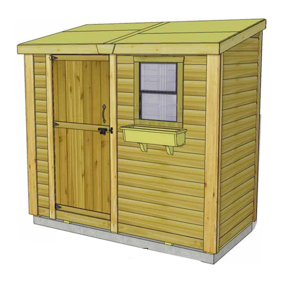
Thank you for purchasing
an 8x4 SpaceSaver Garden
Shed. Please take the time
to identify all the parts prior
to assembly.
Please be aware that it is the
customers' sole responsibility
to acquire the necessary
building permits and or obtain
approval from their local
county, municipality or HOA
prior to purchasing. Generally,
shed structures under 100
square feet do not require
permits in most jurisdictions
in the United States and
Canada.
In the event of a missing or broken piece, simply call the Outdoor Living Today Customer
Support
Line
purchase. It is our commitment to you to courier replacement parts, free of charge,
within 10 business days of this notification. Replacement parts will not be
provided free of charge after the 30 day grace period.
Outdoor Living Today
8x4 SpaceSaver Garden Shed
Bevel Model with Plywood Roof
@
1-888-658-1658
www.outdoorlivingtoday.com
Assembly Manual
September 19, 2022
Optional door
configuration
within
30
days
Page 1
Revision #1.8
of
the
delivery
sales@outdoorlivingtoday.com
of
your
Advertisement

Related Manuals for OLT 8x4 SpaceSaver Garden Shed Bevel Model with Plywood Roof


Summary of Contents for OLT 8x4 SpaceSaver Garden Shed Bevel Model with Plywood Roof
- Page 1 8x4 SpaceSaver Garden Shed Bevel Model with Plywood Roof Assembly Manual Revision #1.8 September 19, 2022 Thank you for purchasing an 8x4 SpaceSaver Garden Shed. Please take the time to identify all the parts prior to assembly. Please be aware that it is the customers’...
- Page 2 What to do before my Shed arrives? • Become familiar with this assembly manual and determine if you can complete the project yourself or will require a professional contractor. • One helper is recommended to assist in construc ng your shed. It generally takes two people two days to assemble a shed.
- Page 3 Foundation Types for 8x4 Garden Shed 45 1/2” 45 1/2” 96” 96” Completed Foundation Concrete Foundation Floor Frame Concrete Slab Foundation: - Slab must be at least the same size as assembled floor frame (45 1/2” x 96”) or larger. - 6”...
- Page 4 Thank you for purchasing our 8x4 Bevel SpaceSaver Garden Shed. Please take the time to identify all the parts prior to assembly. Parts List: D. Miscellaneous Section (Skirting, Trim, Door, Facia & Misc. Parts A. Floor Section 6 - ¾” x 4 ½” x 45 ”...
- Page 5 8x4 BEVEL SPACESAVER HARDWARE PACKAGE Hardware Kit (Provided) x 10 3” 4” x 240 1 1/2” Finishing Nail 2 1/2” x 140 x 170 1 1/4” Square Drive Bit 3/4” x 22 2” Black Headed Drop Latch Door Handle x 1 90°...
- Page 6 Regular Maintenance & Tips to prolong the life of your shed. Before/During Assembly: 1.) Paint each face and edge of your plywood floor with a latex exterior paint. 2.) Caulk wall seams if gaps appear. 3.) Caulk around window framing. 4.) Caulk perimeter between floor plywood and bottom wall plate.
- Page 7 Exploded view of all parts necessary to A. Floor Section complete Floor Section. Identify all parts prior to starting. Note: Floor Footprint is 96” wide x 45 1/2” deep. Exploded Floor Section Plywood Floor Floor Joists (2) Small Floor Joist Frame Large Floor Joist Frame Floor Runners (5)
- Page 8 4th Runner Flush with Floor Framing. Position and attach Floor Runners (1 1/2” x 3 1/2” x 45 1/2”) to completed floor frames with 6 - 2 1/2” screws per Runner. With Floor Joist Frames positioned Make sure Runners are flush with outside together flush, attach with 6 - 2 1/2”...
- Page 9 Note: Plywood is cut slightly smaller than floor framing. Keep plywood seams tight. Position Plywood so it sits almost flush with outside of floor joist framing (see Note). When correctly positioned, attach to all floor joists with 1 1/4” screws. Use screws every 16”. Exploded view of all parts necessary to B.
- Page 10 Starting on side, position a Solid Wall Panel on top of plywood floor. The Wall Panel bottom framing will sit flush with floor framing. Wall siding will overhang the floor. Important: Make sure all walls are aligned in their upright position. If not, water may leak into your shed. Unsure if panel is facing up or down? Recently attached Bottom Plate is on bottom of panel.
- Page 11 With the corner wall attachment complete, position the second rear wall panel in place so bottom 2x3 wall framing is sitting flush with outside floor framing. Wall siding should overhang floor by approximately 3/4”. When positioned correctly, attach both wall panel studs together as per Step 12 with 3 - 2 1/2”...
- Page 12 2x3 wall plate flush with plywood floor. Once again position the 2x3 wall plate so it sits flush on floor and siding overhangs. When correctly positioned, secure Narrow Wall Stud to Side Wall Stud with 3 - 2 1/2” screws. Note: Narrow Wall Panel is only 73”...
- Page 13 Jamb flush with top of narrow wall. Gap on window side. Jamb flush with Door opening siding butt. should be 32” Position Door Jambs flush against narrow and window wall studs and tight to floor. The Jamb is 3 1/2” wide and will sit flush to outside of wall siding. When positioned correctly, secure Jambs using 4 - 2 1/2”...
- Page 14 Siding lines up. Sidings will overlap. Wall framings flush. Align wall framing of Angled Wall Extender and Side Wall so they are flush at the back. The siding for both walls should also align evenly from front to back. With Angled Wall Extender and Side Wall aligned correctly, secure together from the inside with 4 - 2 1/2”...
- Page 15 Siding of Extension Wall. Siding of rear wall. Locate one Wall Extender and place on rear wall panel with siding of extender overlapping that of the rear wall. With 2x3 wall framing aligned, attach Wall Extender to both the Angled Wall Extender framing and the rear wall framing with 5 - 2 1/2”...
- Page 16 Attach Horizontal Wall Cleats (1 @ 3/4” x 3 1/2” x 70”, 1 @ 3/4” x 3 1/2” x 21”) to Wall Extender bottom framing and Rear Wall top framing, so that cleat is flush with extender framing. There is a short and a long wall cleat.
- Page 17 Note: We recommend you drill a 1/8” pilot hole for each screw, to avoid splitting wood. The hole depth should be equal to 3/4 the length of screw. Rear Soffit Boards (2) 96” Mid Rafter Mid Rafter 21 3/4” 48” 21 3/4”...
- Page 18 Rafter ends vertical. Side View Carefully flip completed Rafter Section over so Front Soffit is facing the front and place on SpaceSaver walls. Note: Double check that your Rafter Section is positioned correctly by ensuring the ends of the Rafters are sloped vertically as shown above. Toll Free 1-888-658-1658 www.outdoorlivingtoday.com sales@outdoorlivingtoday.com...
- Page 19 Front Soffit. Rear Soffit. When Rafter Section is positioned correctly, both Front and Rear Soffits will sit approximately 1/8” away from wall siding. This can vary slightly. 90° Metal Brackets With Rafter Section correctly aligned, secure rafters to walls using 90° Metal Brackets. Start with outside rafters and secure 2 90°...
- Page 20 2” overhang There are 3 different plywood roof panel sizes required to complete roof. 48” wide x 32” deep x 2 pcs. 48” wide x 21 3/4” deep x 2 pcs. 4” wide x 53 3/4” deep x 1 pc. Sits on outside of Starting with front left, position a 48”...
- Page 21 Once rear plywood is positioned correctly, attach with 6 - 1 1/4” screws as per Step 39. Position the remaining 3 sheets of plywood on rafters. Position 4” wide strip of plywood on center rafter and attach with 3 - 1 1/4” screws. Line up front/rear with previously attached plywood.
- Page 22 D. Miscellaneous Section Exploded view of all parts necessary to complete the Skirting, Trim, Facia and Miscellaneous Pieces. Identify all parts prior to starting. Not Shown: Door Stops, Flange, Threshold, Rear Trim, Horizontal Door Trim and Roofing Felt) Rear Facia (2) Side Angle Front &...
- Page 23 Skirting meets flush in center. Rear skirting pieces will meet together in the center. Secure with 4 - 1 1/2” finishing nails per piece. Gaps on outside will be covered by Corner Trim pieces later. Complete front and side skirting attachments.
- Page 24 Gap to be covered. Attach Corner Filler Trims where gaps exist in front corners (2 per side). Hammer with 8 - 1 1/2” finishing nails. Position bottom filler just below wall siding. Top filler just below soffit. Gap in middle. Rear Center Corner Filler Trim.
- Page 25 Step 61 before attaching Door Trim. Use Narrow Wall and Above Door Trim as a template to align trim. Flush with Narrow Tight under- Wall stud. Vertical neath soffit. Door Trim. Locate Vertical Door Trim (2 - 1/2” x 3 1/2” x 79”). Position Door Trim flush with outside of narrow wall stud.
- Page 26 To completely trim out rear corners, locate Side Rear Corner Trims (1/2” x 2 1/2” x 88 3/4”) and Rear Corner Trims (1/2” x 5 1/2” x 88 3/4”). Align and attach as per Step 58. Attach Rear Middle Trim (1/2” x 2 1/2” x 88 3/4”) where wall panels come together at rear seam. Attach with 8 - 1 1/2”...
- Page 27 Hint: Use Shim Shingle or extra piece of siding to help space Door at top and bottom. With Hinges attached, position door in opening. You will need some assistance to hold door in place. Important - Drill Pilot holes to prevent splitting. 1/2”...
- Page 28 Side Angle Cut Facia Front Rafter/Facia Nailing Plate. Facia. Locate and identify all Facia pieces: Front & Rear Facia (4) (1/2” x 4” x 50 1/2”). Side Angle Cut Facia (2) (1/2” x 4” x 54 1/8”). In front corner, align side and front Facia together. Front facia will cap side facia.
- Page 29 Attach Facia / Detail Plates to cover seams where Front and Rear Facia pieces come together. Secure with 4 - 1 1/2” finishing nails per piece. Lower interior door stop. 32” door stop. Door Jamb. Attach Upper Interior Door Stop (1/2”...
- Page 30 Window frame. Caulk gap. Screw insert into bottom (thick) part of siding. To reduce possible water from penetrating into the window cavity, caulk gap on both sides of window opening prior to installing Window Insert. Position insert in cavity and screw with 6 - 8 1 1/4” screws. On sides, make sure to screw insert into the thick butt of the siding only.
- Page 31 Attach Door Handle. Handle should be Assemble Flower Box with Assembly Instructions positioned with larger flange to top. Mount included with this Manual on Page 33. Center com- with 3/4” Black Headed Screws. pleted flower box below bottom of window trim and secure with 2 - 2 1/2”...
- Page 32 Optional - Door Configuration on End Instructions. (New Door Jamb and Door Trim.) Install Narrow Wall as per Step 17. Attach Door Header as per 1 1/2” x 3 1/2” x 73” Step 21. Optional Door Jamb. Door Header Position Optional Door Jamb as shown to the right using 6 - 4”...
- Page 33 Outdoor Living Today Flower Box Assembly Instructions Exploded Side Trims (D) View Front Trim (C) End Caps (B) 1 1/4” Parts Lists: Nails (G) A - Base, Rear & Front Box Frames (3pcs) 3/4” x 5 1/2” x 23” B - End Cap Frames (2pcs) 3/4”...
- Page 34 Congratulations on completing your 8x4 SpaceSaver Shed! Note: Our Sheds are shipped as unfinished products. exposed to the elements, the Western Red Cedar lumber will weather to a silvery-gray color. If you prefer to keep the cedar lumber looking closer to the original color, we suggest that you treat the wood with a good wood stain.
Need help?
Do you have a question about the 8x4 SpaceSaver Garden Shed Bevel Model with Plywood Roof and is the answer not in the manual?
Questions and answers