Table of Contents
Advertisement
GETTING STARTED GUIDE
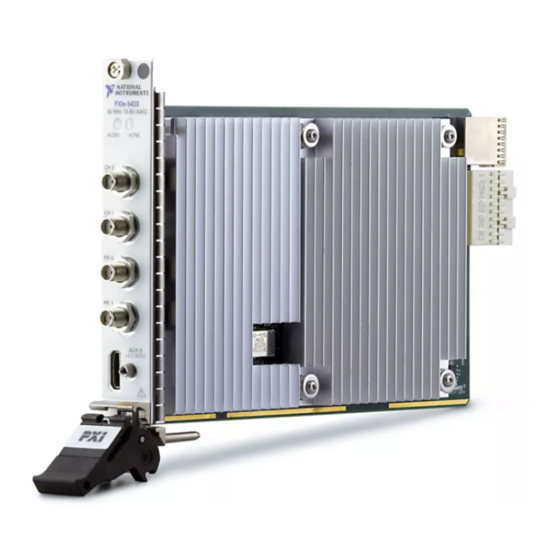
PXIe-5433
80 MHz Bandwidth, 16-Bit PXI Waveform Generator
This document explains how to install, configure, test, and use the PXIe-5433. The PXIe-5433
ships with NI-FGEN driver software, which you can use to program the module.
Note
Before you begin, install and configure your chassis and controller.
Caution
where this symbol is marked.
Caution
a manner not described in this document.
Contents
Electromagnetic Compatibility Guidelines............................................................................... 2
Verifying the System Requirements..........................................................................................2
Unpacking the Kit..................................................................................................................... 2
Other Equipment....................................................................................................................... 3
Preparing the Environment....................................................................................................... 4
Installing the Software.............................................................................................................. 4
Installing the PXIe-5433........................................................................................................... 5
PXIe-5433 Pinout and LEDs.....................................................................................................6
PXIe-5433 SCB-19 Pinout..............................................................................................10
Configuring the PXIe-5433 in MAX...................................................................................... 11
Self-Calibrating the PXIe-5433.............................................................................................. 12
Generating Waveforms with the NI-FGEN Soft Front Panel................................................. 12
NI-FGEN Instrument Driver................................................................................................... 13
Generating Waveforms with NI-FGEN and LabVIEW.......................................................... 13
Troubleshooting...................................................................................................................... 14
Why Is the ACCESS LED Off When the Chassis Is On?...............................................14
What Should I Do if the PXIe-5433 Doesn't Appear in MAX?......................................15
What Should I Do if the PXIe-5433 Fails the Self-Test or Self-Calibration?.................15
Where to Go Next................................................................................................................... 15
PXIe-5433 Firmware Licensing..............................................................................................16
Worldwide Support and Services............................................................................................ 16
This icon denotes a caution, which advises you to consult documentation
You can impair the protection provided by the PXIe-5433 if you use it in
Advertisement
Table of Contents

Related Manuals for National Instruments PXIe-5433


Summary of Contents for National Instruments PXIe-5433
-
Page 1: Table Of Contents
GETTING STARTED GUIDE PXIe-5433 80 MHz Bandwidth, 16-Bit PXI Waveform Generator This document explains how to install, configure, test, and use the PXIe-5433. The PXIe-5433 ships with NI-FGEN driver software, which you can use to program the module. Note Before you begin, install and configure your chassis and controller. -
Page 2: Electromagnetic Compatibility Guidelines
ADEs, refer to the readme for your selected software support. Readmes are available on the driver software DVD and online at ni.com/updates. Unpacking the Kit Refer to the following figure to identify the contents of the PXIe-5433 kit. 2 | ni.com | PXIe-5433 Getting Started Guide... -
Page 3: Other Equipment
Store the module in the antistatic package when the module is not in use. Other Equipment There are several required items not included in your PXIe-5433 kit that you need to operate the PXIe-5433. Your application may require additional items not included in your kit to install or operate your PXIe-5433. -
Page 4: Preparing The Environment
SHH19-MH19-AUX shielded single-ended cable, 1 M (NI part number 784091-01) Visit ni.com for more information about these additional items. Preparing the Environment Ensure that the environment you are using the PXIe-5433 in meets the following specifications: Maximum altitude 2,000 m (800 mbar) (at 25 °C ambient temperature) -
Page 5: Installing The Pxie-5433
The PXIe-5433 is a single-slot module with one backplane connector. The module may be installed into any PXI Express-compatible slot. Ensure the AC power source is connected to the chassis before installing the PXIe-5433. -
Page 6: Pxie-5433 Pinout And Leds
Why Is the ACCESS LED Off When the Chassis Is On? on page 14 PXIe-5433 Pinout and LEDs Front Panel Refer to the following figure and tables for information about the one- and two-channel PXIe-5433 front panel connectors and LEDs. 6 | ni.com | PXIe-5433 Getting Started Guide... - Page 7 5 AUX 0 MHDMR Routes digital trigger and event signals with eight bidirectional PFI lines and provides a +3.3 V power source. The ACCESS LED indicates basic hardware status. PXIe-5433 Getting Started Guide | © National Instruments | 7...
- Page 8 AUX 0 connector is not guaranteed if a third-party HDMI cable is used. Use NI cable assembly SHH19-MH19-AUX for all AUX 0 connections. Do not connect the AUX 0 port on the PXIe-5433 to the HDMI port of another device. NI is not liable for any damage resulting from such signal connections.
- Page 9 AUX 0/PFI 1 Bidirectional PFI line Ground reference for signals AUX 0/PFI 2 Bidirectional PFI line AUX 0/PFI 3 Bidirectional PFI line Ground reference for signals AUX 0/PFI 4 Bidirectional PFI line PXIe-5433 Getting Started Guide | © National Instruments | 9...
-
Page 10: Pxie-5433 Scb-19 Pinout
NI recommends using the SCB-19 connector block to connect digital signals to the AUX 0 connector on the PXIe-5433 front panel. Refer to the following figure and table for information about the SCB-19 signals when connected to the AUX 0 front panel connector. -
Page 11: Configuring The Pxie-5433 In Max
Related Information What Should I Do if the PXIe-5433 Doesn't Appear in MAX? on page 15 What Should I Do if the PXIe-5433 Fails the Self-Test or Self-Calibration? on page 15 PXIe-5433 Getting Started Guide | © National Instruments | 11... -
Page 12: Self-Calibrating The Pxie-5433
• After first installing the PXIe-5433 in a chassis • After any module that is in the same chassis as the PXIe-5433 is installed, uninstalled, or moved • When the PXIe-5433 is in an environment where the ambient temperature varies or the PXIe-5433 temperature has drifted more than ±5 °C from the temperature at the last self-... -
Page 13: Ni-Fgen Instrument Driver
You can run the NI-FGEN examples to demonstrate basic waveform generator applications. Examples display the functionality of the PXIe-5433 and serve as programming models and building blocks for your own applications. LabVIEW, LabWindows/CVI, C, and .NET examples are located at Start»All Programs»National Instruments»NI-FGEN»NI-FGEN Examples. -
Page 14: Troubleshooting
The Fgen Basic Arb Waveform example demonstrates how to get started using arbitrary waveform mode. Complete the steps on the block diagram. In the Resource Name list, select the device name assigned to the PXIe-5433 in MAX. Click Run to start the example program. Troubleshooting If an issue persists after you complete a troubleshooting procedure, contact NI technical support or visit ni.com/support. -
Page 15: What Should I Do If The Pxie-5433 Doesn't Appear In Max
Reinstall the failed module in a different slot. Power on the chassis. Perform the self-test or self-calibration again. Where to Go Next Refer to the following figure to locate more information about using the PXIe-5433. PXIe-5433 Getting Started Guide | © National Instruments | 15... -
Page 16: Pxie-5433 Firmware Licensing
*This item is also installed with the driver software. PXIe-5433 Firmware Licensing Software is licensed pursuant to the software license agreements provided with the software or, in the absence of such license agreements, the National Instruments Software License Agreement available at ni.com/legal at the time of purchase. - Page 17 United States, visit the Worldwide Offices section of ni.com/ niglobal to access the branch office websites, which provide up-to-date contact information, support phone numbers, email addresses, and current events. PXIe-5433 Getting Started Guide | © National Instruments | 17...
- Page 18 NI trademarks. Other product and company names mentioned herein are trademarks or trade names of their respective companies. For patents covering NI products/technology, refer to the appropriate location: Help»Patents in your software, the file on your media, or the National Instruments Patent Notice at . You can find patents.txt ni.com/patents...
Need help?
Do you have a question about the PXIe-5433 and is the answer not in the manual?
Questions and answers