
Summary of Contents for Kelant S400S
- Page 1 S400S 3D PRINTER PRODUCT MANUAL S400S-3D printer User Manual Shenzhen kelant science and technology Co., Ltd.
- Page 2 Thank you choosing Kelant Combat S400S printer! If you have any questions, please contact customer service or log on the official website www.kelandi.cn Facebook group: https://www.facebook.com/groups/KelantOfficial Copyrighted by “shenzhen Kelant Technology co.,Ltd”All rights reserved...
-
Page 3: Table Of Contents
1、Packing List ............................1 2. Precautions ............................. 2 3、Technical Specification ......................3 4、Printer Overview ........................... 4 5、Assembling ............................5 6、Touch screen Introduction ..................... 9 7、Menu directory ..........................9 8、Leveling ............................11 9、Slice software description ....................14 10、First print instructions ......................22 11、FAQ and machine maintenance .................. -
Page 4: 1、Packing List
1、Packing List Kelant S400S 1PCS Z axis 1PCS Resin Vat 1PCS Handle 1PCS Hinge 2PCS Cover 5PCS Cover pillar Platform Base Screws 5PCS Hand screw 8PCS 1PCS 1PCS Power adapter Build Plate 1PCS 1PCS... -
Page 5: Precautions
2.Precautions Please contact customer service if you have any questions after you received the printer Keep the Kelant combat S400S and its accessories away from Children Use printer at room temperature , Avoid direct sunlight and dusty environment Kelant Combat S400S must NOT be exposed to water and rain. -
Page 6: 3、Technical Specification
3、 Technical Specification Printing parameters System Kelant Operation 3.5-inch touch screen Slicing software ChiTu DLP Slicer/ChiTuBox Connectivity USB Disk Specifications Technique LCD Shadow Masking Light Source UV-LED(Wavelength 405nm) XY Resolution 75 microns(2560*1600) Z axis accuracy 25 microns Suggested layer thickness 0.025~0.2mm... -
Page 7: 4、Printer Overview
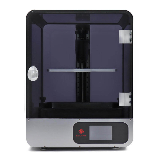
4、Printer Overview Acrylic touch screen Platform Base Screw DC interface Screw rod platform Resin Power switch Resin Vat Screw USB interface... -
Page 8: 5、Assembling
5、Assembling 1、 Place Printer base on the desktop. 2、 Mount the Z-axis to the main unit as shown. (Materials required: 4 pcs screws ,M6*15 ) 3、 Lock the screw of the lead screw and the motor coupling and insert the upper limit switch plug. - Page 9 4、 Take out the four B1, B2, and B3 columns. The groove on the column is inserted into the main plate of the main unit in the direction of the red arrow (if you can't insert it, loosen the machine screw on the column) and lock the four columns.
- Page 10 6、 Remove the three B4 and B5 columns. The groove on the B4 column is oriented in the direction shown by the red arrow. Use the four S1 screws to lock the three columns. B4(1PCS) B5(2PCS) 7、 Remove the column B6, acrylic A2, and tear off the protective film of the acrylic A2.
- Page 11 9、 Remove the hardware kit fist, use one S2 screw to mount the handle on the A4 board, four S3 screws will hinge on the B3 column, and then use the six S4 screws to mount the acrylic A3. A3(1PCS) A4(1PCS)...
-
Page 12: 6、Touch Screen Introduction
6、 Touch screen Introduction main menu System Tool Print Service Information Network Calibrate and Full exposure print Manual... -
Page 13: 7、Menu Directory
7、Menu directory Delete Current file Enter the System Menu Click start printing Enter the tools Menu Return to print Menu Printing Information Turn on / off Sound Return to system menu System Move Z-axis Change Language (Chinese/English ) Official website and after sale contact Move up Z-axis Product information Move down Z-axis... -
Page 14: 8、Leveling
7、 Leveling The machine has been leveled at the factory, and you can print with the flatbed installed. If the printing does not stick to the platform, please follow the steps below to level 1、 Take out the assembled printing platform and loosen the four screws on the left and right sides of the cradle head, so that the cradle head can move up and down freely. - Page 15 automatically. When the Z axis is down, if there is an abnormality, click "STOP" to stop the drop. 6、 Press the top of the platform with your hand, so that the four corners of the platform are evenly attached to the 2K LCD screen. Tighten the screws on the left and right sides of the cradle head diagonally, and twitch the four corners of the A4 paper.
- Page 16 height. 8、 Upward platform about 100mm, check whether the LCD screen works normally: as shown in the figure, press the touch screen "Tool" → "calibrate" → "Next", if the 2K forming screen can display the grid completely, it means the LCD screen works normally. ,as the picture shows.
-
Page 17: 9、Slice Software Description
9、Slice software description 1、Installation instructions The slicing software is located on the USB Drive, under the slicing software folder Run the slicing software installer (double-click the software icon). According to the following figure for installation:... - Page 18 Click the top left corner of the software interface, and click the language to change the language Settings. 3、Import the configuration Click on the upper left corner of the software interface, click help, click Import configuration, select KLD-S400S.cfg. in the USB Drive folder "切片软件 Slicer "...
- Page 19 4、Introduction to slicing interface Click "open file" → "select file" → "open" at the top of the interface to import your own 3d format model (.stl file). Click the model with the left mouse button, and change the position, placement Angle, zoom in and zoom out of the model image by operating the function options on the left side of the software interface。The menu bar at the top of the software interface is respectively for opening files, saving files,...
- Page 20 5、Slice parameter setting First click on the slicing settings of the software interface, and then set the machine, resin, print, fill, Gcode, advanced settings, please refer to the following figure::...
- Page 21 The resolution and size must be set correctly according to the above figure, and the setting error will cause the size of the printed model to be enlarged or reduced.。 Please use the default settings if you use our original resin. Please refer to the recommendations below for self-matching of third-party resin.
- Page 22 Bottom lift distance(mm) : Recommended value 12, print the bottom of the stripping height. Lift distance(mm) : Recommended value 10, lifting height of demoulding for common layer. Bottom lift speed (mm/min) : Recommended value 80, bottom drawing lifting speed. Lifting speed(mm/min) : Recommended value is 80, lifting speed of demoulding for common layer.
- Page 23 Support type Settings can be divided into fine, medium, thick. Each setting has a corresponding parameter setting. Thin: the contact area between the support and the model is small, easy to remove the support; Coarse: the contact area between the support and the model is large and stable.
- Page 24 7、First section instruction Load the model in the main interface of the slicing software (7-1). Select the model to the appropriate Angle as shown in figure (7-2). Under normal circumstances, the model rotation is best placed at a 45-degree Angle. During the placement, it should be considered to avoid the problem that the support cannot be added or removed from the completely suspended position.
-
Page 25: 10、First Print Instructions
The section (7-7) can be started after the parameter setting of the section is correct. After the section is completed, the preview bar needs to be dragged from the top to the bottom (7-8), and the bottom of the model is checked for completeness. - Page 26 1、Print Please insert USB disk into printer USB port or connected wifi ,then wear gloves,slowly pour the resin to resin VAT until it reaches 1/3 volume of it . take off gloves ,select test file or your own file ,as photo shows, and start printing , During printing .
-
Page 27: 11、Faq And Machine Maintenance
" → set the exposure time as 20 seconds "next", wait for the end of exposure, a layer of thin film will be solidified at the bottom of the material groove. Finally, use a yellow plastic spatula to eradicate the thin film and clean the solidified material on the printing platform. - Page 28 at Build plate. Solution: Increase the bottom exposure time (60-100 seconds) and bottom layers (3-10 layers). 2, print the model cracked, hole or only a base Because the curing time of the common layer is not enough. The solution is to increase the normal layer curing time by 1 to 3 seconds.
- Page 29 Error Error Possible causes Solution types code USB error M_3e bad contact Reinsert the u disk or replace the USB disk M_800 USB timeout Reinsert the u disk or replace the USB disk error M_1000 cannot find Reinsert the u disk or replace the USB disk memory M_2000 parameters...
- Page 30 The fault phenomenon Probable cause The solution The z-axis doesn't move Motion configuration Download the latest firmware parameters missing update from the official website 2K LCD display is incomplete or FPGA firmware missing Download the latest firmware no image display update from the official website The LCD cable is loose Remove the back board of the...
- Page 31 If there is a failure of the printer with a failure code, the problem is not solved after handling according to the corresponding solution, or there is a failure of the machine without a failure code prompt, and the fault type is uncertain, please record the failure phenomenon video and send it to the after-sales service staff in time, and we will answer your questions.
Need help?
Do you have a question about the S400S and is the answer not in the manual?
Questions and answers