Table of Contents
Advertisement
Advertisement
Table of Contents

Related Manuals for Termodinamik ECS 70


Summary of Contents for Termodinamik ECS 70
- Page 1 H E AT I N G S Y S T E M S STEEL BODY CENTRAL HEATING HOT WATER BOILER ECS 70 / 85 / 100 / 150 / 200 / 250 / 300 / 350 / 400 500 / 600 / 700 / 800 / 900 / 1000 CALOR SRL Str.
-
Page 2: Technical Specifications
TECHNICAL SPECIFICATIONS MODELS Unit ECS 70 ECS 85 ECS 100 ECS 150 ECS 200 Heat power kcal/h 70.000 85.000 100.000 150.000 200.000 81,4 98,8 116,2 174,3 232,4 Heat input kcal/h 76.500 92.600 109.900 164.800 219.800 88,9 107,6 127,7 191,5 255,5 Max. - Page 3 TECHNICAL SPECIFICATIONS MODELS Unit ECS 600 ECS 700 ECS 800 ECS 900 ECS 1000 Heat power kcal/h 600.000 700.000 800.000 900.000 1.000.000 697,3 813,6 929,8 1046 1162,2 Heat input kcal/h 659.300 769.200 879.100 989.000 1.099.000 766,3 1021,7 1149,4 1277,3 Max. Operating Temperature Temperature control range 30-90 30-90...
- Page 4 GENERAL DIMENSIONS AND TECHNICAL SPECIFICATIONS...
- Page 5 GENERAL DIMENSIONS AND TECHNICAL SPECIFICATIONS Operating Test Water Weight Shaft Going Expansion Filling Pressure Pressure Capacity (kg) Turning Going Discharging (bar) (bar) R2" " R3/4" R2" " R3/4" R2" " R3/4" R2" " R3/4" " R1/2" R3/4" " R1/2" R3/4" "...
-
Page 6: General Information
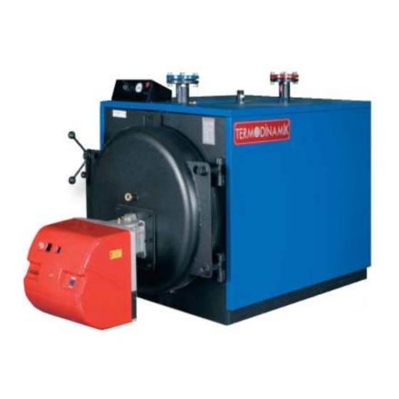
APPLIANCE CHART Boiler frame Bearer Supports Hinge Central System Going Water Connection Boiler Flange Shaft Pipe Front Lid Back Lid Central System Turning Water Connection Bursting Lid Safety Line Filling – Discharging GENERAL INFORMATION This product, running on liquid or gas fuels, is a three-pass steel central heating boiler which generates water at maximum 90C for heating purposes. -
Page 7: General Warnings
GENERAL WARNINGS Please read the instructions and warnings in this manual before installation of the boiler and operation of the appliance. The use of appliance not recommended by the manufacturing company and not specified in this manual may cause fire, electric shock and injuries. - Page 8 Please do not use the boiler for the purposes not intended. This appliance has been designed to generate water at maximum 90C for the heating system. The boiler room should be in compliance with the specifications and regulations related to the discharge of waste gas. For the operation of the ECS boilers in compliance with gas-burning appliances and efficiency directives, please use EN 676 (gas fuel) or EN 267 (liquid fuel) certified boilers.
- Page 9 EXEMPLARY INSTALLATION CHART Closed Expansion Tank and Detailed Pipe Installation Central System Turning Central System Going Safety Line Circulation Pump Circulation Pump (Extra) Expansion Tank Valve (for the 1 Pump) Valve (for the 1 Pump) Valve (for the 2 Pump) Valve (for the 2 Pump) Filling Valve...
- Page 10 EXEMPLARY INSTALLATION CHART Open Expansion Tank and Detailed Pipe Installation Central System Turning Central System Going Safety Going Circulation Pump Circulation Pump (Extra) Expansion Tank Valve (for the 1 Pump) Valve (for the 1 Pump) Valve (for the 2 Pump) Valve (for the 2 Pump) Filling Valve...
-
Page 11: Installation Of The Appliance
INSTALLATION OF THE APPLIANCE MODEL Minimum Ground Sizes ECS 70 1080 X 960 X 200 mm ECS 85 1080 X 960 X 200 mm ECS 100 1080 X 1110 X 200 mm ECS 150 1080 X 1400 X 200 mm... -
Page 12: Control Panel
Assembly Precautions The assembly of the system and putting it into use should be performed in accordance with the current regulation, standard and this manual. A proper installation circuit should be installed in order to protect the boiler against flue gas condensation. Power connections should be installed in accordance with the current standards and regulations. -
Page 13: Cleaning And Maintenance
Have the AUTHORIZED SERVICES OF TERMODINAMIK perform the controls specified in the maintenance instructions on the next page. This is critical to ensure both... - Page 14 BOILER MAINTENANCE PLAN PIPING Piping on the boiler Check if there is any leakage in the piping system on the boiler and system. Make sure there are pipe bearing supports are located where needed. Ventilation Check all ventilation pipes and their connections. Check if there is any gas leakage in all as pipes.
Need help?
Do you have a question about the ECS 70 and is the answer not in the manual?
Questions and answers