Table of Contents
Advertisement
Quick Links
Table of Contents
1.
SPECIFICATIONS ...................................................................................................... 2
2.
INSTALLATION .......................................................................................................... 4
2.1.
Introduction .................................................................................................................................. 4
2.2.
Important ..................................................................................................................................... 5
2.3.
Power Connection ....................................................................................................................... 5
2.3.1.
2.3.2.
2.4.
Communication Connections ...................................................................................................... 6
2.4.1.
2.4.2.
2.4.3.
2.5.
Traffic Light Control (D841) ......................................................................................................... 8
2.5.1.
2.5.2.
2.6.
Setup Command .......................................................................................................................... 9
2.6.1.
2.7.
Scrolling Messages (K802 firmware in D841 Only) .................................................................. 12
2.8.
Mounting Options ...................................................................................................................... 12
2.8.1.
2.8.2.
2.8.3.
3.
ERROR MESSAGES ................................................................................................ 14
APPENDIX A : SUPPORTED PROTOCOLS .................................................................... 15
008D-600-150
D841/D850 Installation Manual
AC variant .................................................................................................................. 5
DC variant .................................................................................................................. 5
Earthing Requirements for Cable Shields ................................................................. 6
Serial Connection ...................................................................................................... 6
Ethernet (Optional) .................................................................................................... 7
Sending the Setup Command ................................................................................. 11
Wall Mounting .......................................................................................................... 12
Weather Hood (Optional) ......................................................................................... 12
Mounting Plate (Optional) (D841 only) .................................................................... 13
Page 1
Advertisement
Table of Contents

Related Manuals for Rinstrum D841

Summary of Contents for Rinstrum D841
-
Page 1: Table Of Contents
From an External DC Source (Serial and Ethernet communications variants) ..8 2.6. Setup Command .......................... 9 2.6.1. Sending the Setup Command ................. 11 2.7. Scrolling Messages (K802 firmware in D841 Only) ..............12 2.8. Mounting Options ........................12 2.8.1. Wall Mounting ......................12 2.8.2. -
Page 2: Specifications
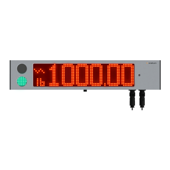
D841/D850 Installation Manual Specifications Display D841 – Full LED Dot Matrix with up to seven (7) full alpha Display numeric characters with decimal point at 120 degrees viewing angle. • Character size (H x W) – 100mmx60mm (4"x2.4") • 14 x 64 LED matrix at 14 x 8 LEDs per character •... - Page 3 Example: With the count set to 20, an indicator displays 00 at zero load. The D841/D850 will also show 00 at zero as there is no leading zero blanking. NTEP is the National Type Evaluation Program in the US.
-
Page 4: Installation
Installation 2.1. Introduction The D841 and D850 are super bright LED displays that feature full alpha numeric characters. These displays are capable of interpreting and displaying formatted weight transmissions from digital weight indicators. Additionally, they can be used to display text. -
Page 5: Important
D841/D850 Installation Manual 2.2. Important The D841 and D850 remote display units contain precision electronics and must not be subjected to shock, excessive vibration, or extremes of temperature, either before or after installation. The serial and power inputs of the displays are protected against electrical interference;... -
Page 6: Communication Connections
Figure 4 - DC power supply socket connection 2.4. Communication Connections The D841 and D850 remote displays are available with two different communication connection types, RS232/RS485 serial and Ethernet. On power up, the display will attempt to automatically detect one of the communication protocols described in Appendix A. -
Page 7: Ethernet (Optional)
D841/D850 Installation Manual Baud Rate and Parity Baud Rate, Parity and Data Bits are automatically detected. The baud rate can be 2400, 4800, 9600 or 19200. Parity and Data Bits supported are as follows: Parity Data bits Examples Description... -
Page 8: Traffic Light Control (D841)
Figure 9 - Ethernet socket connections 2.5. Traffic Light Control (D841) The traffic lights can be controlled by a control character in the supported protocols (refer Appendix A for supported protocols) or by digital inputs available on the communication connection socket. -
Page 9: Setup Command
D841/D850 Installation Manual communications connector. The 5-24VDC supply is then run through the switching control device before been connected to pins 5 for RED and/or 6 for GREEN as per the diagram below. Figure 11 - Driving traffic lights from external DC source 2.6. - Page 10 D841/D850 Installation Manual Reset String: Character Number Description Function Description 0x07 = Control Character BEL 0x01 = Control Character SOH - Start of Header Configuration String: Character Number Description Character Number Description Function Description 0x02 = Start of Transmission Annunciator...
-
Page 11: Sending The Setup Command
The Configuration String can be streamed from a PC running terminal software such as "RealTerm", Android App "Slick USB" or similar. Alternatively, you can use the custom string format in the Rinstrum R400 series indicators to send the string (this method cannot currently be used for displays with Ethernet option). -
Page 12: Scrolling Messages (K802 Firmware In D841 Only)
2.7. Scrolling Messages (K802 firmware in D841 Only) Scrolling messages are supported in the D841 using K802 firmware. The serial data string must be set to 9600 Baud Rate, No Parity, 8 Data Bits and 1 Stop Bit (9600 N81) and be framed with <SOH> and <ETX>. See Protocol 41 in the Protocol Manual for more information. -
Page 13: Mounting Plate (Optional) (D841 Only)
D841/D850 Installation Manual 2.8.3. Mounting Plate (Optional) (D841 only) The optional mounting plate for the D841 supports VESA, RAM and pole mounting. Figure 13 - VESA, RAM and Pole mounting examples Figure 14 - Optional mounting plate 008D-600-150 Page 13... -
Page 14: Error Messages
D841/D850 Installation Manual Error Messages Error Description Underweight - the weight is below the minimum allowable weight reading as per status. Check source device. Overweight - The weight is above the maximum allowable weight reading as per status. Check source device... -
Page 15: Appendix A : Supported Protocols
Protocol commonly used Traffic display multi by indicators from: light support zero support support Ranger A Rinstrum, GSE, HBM & PT Ranger B Rinstrum Ranger C Rinstrum GSE, HBM & PT Ranger D Rinstrum PCMODE Custom software RINCMD Rinstrum & GSE... - Page 16 D841/D850 Installation Manual Notes: Page 16 008D-600-150...
- Page 17 D841/D850 Installation Manual Notes: 008D-600-150 Page 17...
Need help?
Do you have a question about the D841 and is the answer not in the manual?
Questions and answers